Bob's Hi-Fi Tube Amp Page
(c) 2006 Robert B. Richards, All rights reserved.
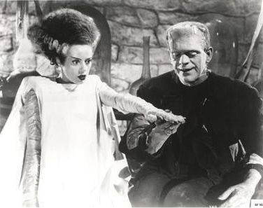
Mr. and Mrs. Frankenstein wanted me to build them a Hi-Fi tube amp...
So I told them I'd look into it.
Most of this page is arguably more of a journal of the best
of my research and thinking on the subject of Hi-Fi tube amp design (as of
2005-7), rather than just a presentation of my amp (see below). It represents
the path I went while developing what would become my "ultimate"
circuit. I studied dozens of tube audio magazines that my old engineering
tech buddy Matt Kamna had accumulated from the 1990's, I read many articles
from the late 1950's ("The Golden Age of tubes") that were considered
top notch, I spent many many many hours scanning the web for anything that
looked relavent and accurate (most wasn't very accurate). I took what I learned
from these sources and talked with Matt Kamna (who's particularly knowledgable
about tube audio design), and we did several experiments to clear up any questions.
Sorry if some of this page is redundant or incomplete. I added
to or updated it many times, over time.
Jump to Final Schematic
and Circuit Calculations.
Jump to Test Results
of finished amp.
Why Tubes?
When I heard all the noise about Tube Hi-Fi being worth it and
better than transistors back in the early 1990's, I laughed and cited the
whimpy output impedance of a low feedback amp which will cause the speakers
to sound "warmer" when it lets them have their resonance around
70HZ, and I pointed out that my Hafler DH-220 power amps are sounding very
nice. I recommended these people work on building better speakers, and working
with the acoustics of their listening room, if they wanted to make a real
improvement. The thing that got me to look closer at tubes was the realization
that in guitar amp land (I'm an audiophile and a guitarist), where
you overdrive tubes for effect to get the "bluesy" sound, tubes
easily sound better to my ear. When I got the desire to build a great tube
guitar amp, I realized that I needed to get inside the "how" and
"why" of this difference, if I was going to make the best possible
amp.
Matt turned me on to the concept of distortion spectrum shape,
what affected it and why. I learned that feedback causes harmonic distortion
products to extend way out (above in frequency) from a fundamental stimulus
frequency. I also learned that any well balanced circuit topology will generate
only odd harmonic distortion products. While crunching numbers on a few tenative
designs of my own, I realized that the extended harmonic distortion products
created by the feedback circuit could result in slewing related distortions
downstream, which sound particularly bad. It occured to me that these distortions
could be so transient in nature that it might be very hard to measure them
effectively using conventional methods.
I've been told that tubes are inherantly significantly more
linear than transistors, and therefore need less negative feedback to get
an acceptable distortion figure. Tubes can even be used with no feedback at
all, which apparently gives you the best sounding distortion spectrum shape.
When tubes are used in an unbalanced circuit topology, especially with little
or no feedback, the distortion they do have is more "natural" sounding
- much closer to how the ear distorts. The DeHavilland SE amp which has no
feedback at all won best sound of the Hi-Fi tradeshow a few years back. If
it weren't for the way most electromagnetic transducers need the damping
effect of a very small amplifier output impedance to control their resonance
(usually around 70 HZ), which high feedback amps have (tube or transistor),
it would seem ideal to have no feedback at all.
On this page, I explore this and whatever else seemed relevant.
So the journey Begins:

Harmonic and Intermodulation Multiplication:
One thing I didn't know about before talking with my old tech
friend Matt Kamna, is the concept that negative feedback loops will cause
the endless recirculation of distortion products that each time around the
loop generate new "higher order" distortion products (both harmonic
and intermodulation (I.M.)), when they re-mix in a non-linear way with the
incoming signal (usually in the front-end stage - where the negative feedback
mixes back into the direct signal path).
Because most of these distortion products are of progressively
higher and higher order (higher frequency, relative to the fundamentals) they
are more likely to be perceived by the ear negatively (less masked by the
findamental - and less likely to be pleasantly musically related to the fundamental).
Higher order products can also cause slewing related problems, especially
in a feedback amplifier (or if there's a feedback amplifier downstream). Constantly
regenerated I.M. sum and difference products will be all over the place in
frequency, not just above the fundamental as with harmonic distortion products.
The probability of them being pleasantly musically related to the fundamental
is next to zero. This could amount to audio frequency noise generation that
would track the music, even when the distorting frequencies are out of band
(substantially supersonic).
Although seemingly below the level of conscious perception (according
to the distortion meter when one or two frequencies are applied), these higher
order distrotion products are believed to be less natural sounding and even
fatiguing over time in the real world. Perhaps because complex music is likely
to be generating hundreds of little "bursts" of various distortion
products all over the spectrum, effectively constantly, but transient in nature
so hard to measure, especially with just one or two sinewaves applied. It's
thought that these hundreds of low level distortion products may add up to
something significant, and/or cause slewing downstream. From this, it has
been suggested that conventional methods of distortion analysis may not be
adequetly reflective of the real world situation. Without a spectrum analyzer,
there would be no good way to see the steady-state version of this. The dynamic
version of this may have been called transient intermodulation distortion
(TIM) and is difficult to display and quantify.
In the real world, there are usually many different sounds mixed
together, generating many different distortion products with whatever non-linearity
exists in the feedback loop or anywhere else. Any distortion products generated
in the feedback "re-mixer" port will then re-circulate endlessly
around the feedback loop, generating more distortion products each time around
the loop. This is fairly easy to see with a good spectrum analyzer.
Is Feedback Needed?
Transistors are generally too non-linear to ever go without
substantial feedback. Since most transistor amplifiers (and op-amps up stream)
use rather large amounts of negative feedback (20-120dB), they are highly
likely to have excessive distortion product regeneration (products extending
way way way out from the fundamentals). They will also thereby have a higher
incidence of slewing (particularly bad sounding). Tubes, both triodes and
ultra-linear mode pentodes (even run push-pull) are linear enough to avoid
global feedback (ultra-linear operation is a form of local negative feedback).
Matt Kamna demonstrated this to me on his bench. But then the output impedance
of the amplifier is several ohms, which throws off the calibration of any
passive crossover in a speaker system, and gives poor damping of the substantially
reactive transducer motor. When driven from other than a zero ohm source impedance,
the impedance variations of most speaker drivers will be reflected in their
acoustic output. The typical resonance around 50-100 HZ will be further reinforced,
instead of damped, by the increase in output stage gain that it causes. The
impedance at this resonance can easily be 4-6 times the rated or midband impedance.
The frequency response may need to be re-calibrated with a calibrated mic
and pink noise at the listener position. The bottom line concensus seems to
be to use about 8dB of global or semi-global negative feedback, so the reactive
nature of the tranducers are kept in check enough, and so the distortion product
recirculation and potential slewing doesn't get too significant.
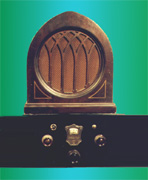
An Atwater Kent with a Bosch cathedral speaker from the 1920's.
Handling Supersonics:
Although humans can only hear up to 15-20kHZ, many musical
instruments and sounds in nature will contain energy that goes substantially
above that. A high quality recording will include this, and a low quality
recording may well have distortion products and/or digital noise energy in
the super-sonic range. If an amplifier can't handle these energies in a linear
way, it will cause the generation of various distortion products, and may
well be in a state of slewing much of the time. Even when the input to output
bandwidth of an amplifier is limited to say 20 - 20kHZ, the feedback loop
will typically be reactive to a much wider bandwidth, largely out of necessity
to avoid phaseshift instability when feedback is employed, and this location
of the circuit can generate it's own supersonic distortion product energies.
The linearity of each part of an amplifier therefore needs to be quite good
to above 100kHZ, and a single "dominant" (or first) pole must roll
off the feedback loop gain to below one, before additional phase shift from
other poles in the feedback loop can cause the feedback to become mostly or
all positive, thereby rendering the amplifier unstable.
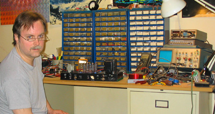
Me at my home bench with one of my guitar amps.
Here's part of an interview that's
relevent:
From the Archives of Positive Feedback
Magazine: An Interview with Scott Frankland by Mike Pappas:
Frankland: That problem is harmonic multiplication.
Pappas: Could you explain what that means?
Frankland: When we apply feedback around
a circuit we create a path for harmonic distortion products to loop through
the amplifier. At each pass they intermodulate with the audio signal, creating
sum & difference products at the output.
Pappas: How is this different from ordinary
IM distortion?
Frankland: Ordinary IM distortion creates
a finite number of sum and difference products. With recirculation, however,
the IM products have the potential to multiply themselves to infinity. This
was analyzed by Baxandall in the late '70s.
Pappas: How is this possible?
Frankland: Let's say we have an amp that
produces purely second-order distortion-a triode amp at low power levels,
for example. When 2f loops around, it intermodulates with 1f (the fundamental)
to produce 3f; 3f then loops around to produce 4f; and so on. This repetitive
looping generates a flood of high-order products that runs through the circuit
like bad adrenaline.
Pappas: That sounds ugly.
Frankland: And that is the main reason
why feedback has become so unpopular lately.
Pappas: So harmonic recirculation turns
out to be a fundamental flaw in feedback theory?
Frankland: Feedback per se is not inherently
flawed. This becomes apparent once we understand what makes feedback turn
ugly. What is flawed is the active device around which feedback is applied.
Baxandall showed that, although feedback converts low-order products to high-order
products, the feedback still acts to reduce the overall distortion.
Here's a bit from Claus Byrith:

My View of Harmonic Distortion:
If you figure out what note on a piano each harmonic distortion
product is, and then play the notes in conjunction with the fundamental, you
find that the 2nd harmonic is the same as the fundamental but one octave higher
(unless below about 100 HZ where the curve skews slightly - see the Audio
Cyclopedia). The 3rd harmonic forms a major chord with the fundamental, which
will enhance a song that is in a major scale, but will cause "dissonance"
in a song that is in a minor scale. From there on, the higher order harmonic
distortion products are hit/miss as to whether or not they are pleasantly
musically related to the fundamental. When you generate harmonic distortion
products that extend way out from the fundamental, you get an accumulation
of "notes" that aren't likely to be pleasantly musically related
to the fundamental. It could be argued that this "noise" is then
"modulating" the waveform. I wonder if there's a test for this kind
of thing (?) This is the practical perspective on why higher order harmonics
are bad.
The presence of the 2nd harmonic is arguably always good (when
it isn't the result of bad linearity and therefore high I.M. product generation).
When measuring harmonic distortion, it is therefore arguable that the 2nd
harmonic could be ignored. One might ask, "How far down are the harmonics
after the 2nd?". If you symetrically clip a sinewave, you will generate
only odd harmonics. If you run a sinewave through a circuit where gain varies
as a function of position on the dynamic range (typical of a heavily loaded
pentode, for ex.), you get mostly even harmonics (maybe not as bad) but also
generation of intermodulation (I.M.) products (very bad). The ideal circuit
would generate only the 2nd harmonic, and have a very rapid rolloff of any
higher order harmonics. A single-ended triode with a follower buffer seems
to achieve this the best. The buffer is needed to keep the generation of I.M.
products down.
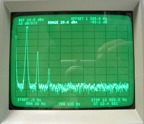
This is a single ended triode. The best distortion spectrum
shape I've seen.

After researching this extensively and doing several listening
tests, I've decided that I must design and build a great but reasonable tube
amp, and further research this.
Some of my Notable Research:
I found a slight variation of the following circuit on the web.
It was designed by Claus Byrith, a long time recording engineer and circuit
design hobbyist. After reading his 35 page write-up about how he designed
it, I was left very impressed. It's got three feedback loops that seem to
bring out the best in the single-ended EL34, and set the output damping factor
to about one. Enough feedback (8dB) to reduce the output impedance and distortion
to a more desirable level without being so excessive as to generate too many
higher order harmonics. He claims that on the bottom line, the second harmonic
distortion product is higher than the third (very desirable). He also claims
that the non-linearity that causes I.M. distortion products in the output
stage is somewhat counteracted by a similar non-linearity in the driver stage,
which adds inverted and thereby allegedly largely cancels. He did research
on five different SE output topologies to find which had the most power and
least distortion. Taking the screen grid to the 50% tap on the Lundahl transformer
(local negative feedback), and using the transformer secondary in the cathode
circuit (also local negative feedback) was the winner. The global feedback
is adjustable from zero to 10 dB. He says he likes the sound of 8dB the best,
using Dynaudio speakers with passive crossovers. If I tri-amp, I may use a
circuit something like this for my tweeter amp.
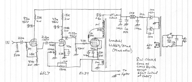
This is my redrawing, with the only difference being that I
substituted the 6SL7 in place of the 12AX7 that Claus was using. The 6SL7
is a more linear tube according to Matt Kamna, who has personally measured
the linearity of virtually all triodes that were ever made, and who has the
equipment and know-how to do it right. I haven't yet changed the part values
to optimize for the 6SL7. Claus got a pretty clean 8 watts out of the single
ended EL34. Using a more conventional SE topology with no feedback at all,
we were only able to get about 4 watts before the distortion got above about
5%. The use of local feedback (ultralinear screen grid connection and xfmr
secondary in the cathode) seems to be responsible for this improvement. When
the feedback (in any form) lowers the output impedance of the amp as seen
by the speaker, the passive crossover in the speaker won't be thrown off as
much, and variations in the impedance of the speaker won't cause gain variations
as much. Each of these issues are substantial. Type his name into google if
you want to access his 35 page write-up. He also did a write-up on an EL34
push-pull amp he designed.
Fixing the Push-Pull:
Any circuit that by design is symetrical (thereby arguably cooler
looking on paper) will generate odd harmonic distortion products, but not
even (or at least a lot less even). Although this shows a better distortion
number on the Audio Precision meter, there are those who believe that a more
natural distortion spectrum makes music feel better, and on the nuance level
be more believable. Since the 2nd harmonic, which is the same note as the
fundamental but one octave higher, is downright good sounding, many people
want to use a topology that will have the more natural distortion spectrum
with the 2nd harmonic distortion product dominating over the 3rd. I think
this is the main reason why some people use single ended output stages (there's
also the microdynamic linearity issue). It was found that by throwing off
the AC drive balance to the push-pull output stage by less than a dB, while
maintaining the DC balance, the 2nd harmonic distortion product would dominate
the 3rd significantly. With tubes, tolerances are sloppy enough that any random
push-pull amp will probably already have a higher second than third harmonic
(the Dynaco 70 did despite the 20dB of feedback))(part of the reason tubes
sound better than transistors?). This article shows that you can design in
an AC imbalance, while maintaining DC balance, and further shift the ratio
of 2nd and 3rd harmonics in a favorable way.
This article by Rickard Berglund was published in Sound Practices
Winter 94/95 issue. Matt Kamna and I verified that this idea works on the
bench. Notice the plate resistor ohms differential on the 6SN7 (66Kohm vs.
33Kohm):
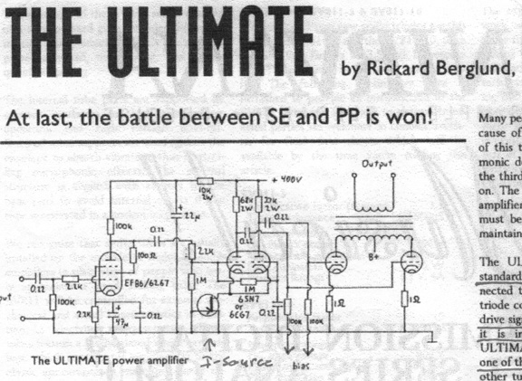
Rickard Berglund found that by throwing off the AC balance of
the drive to the output tubes by approximately 2.3dB, while maintaining the
DC balance, you get a more natural harmonic distortion spectrum, with the
2nd harmonic being higher than the 3rd. The problem with this circuit is that
you might need feedback to lower the output impedance for speaker damping
and impedance control, and any feedback will largely un-do the AC imbalance
leaving you with a more limited headroom on the driver stage, which because
of global feedback may well be over driven. If however you were driving only
a 7 ohm ribbon tweeter (allegedly very resistive), and using a crossover that
was ahead of the poweramps, you might not need feedback at all. That's apparently
a good way to go. I read that Jim Fosgate (designer of Dolby Labs best surround
sound sythesizer topology - "ProLogic 2")) is using a no-feedback
tube amp on his tweeters of his tri-amp'd speakers.
Jim Fosgate's Amps:
Jim Fosgate is perhaps one of the main pioneers on the planet
when it comes to surround sound. He's the expert on turning a two channel
"stereo" feed into a five channel surround sound experience. He's
apparently the main engineer behind the Dolby Laboratories Pro-Logic 2 surround
sound synthesizer. The reviews I've read say his Dolby Pro-Logic 2 is the
best in the world at what it does; even better than the Lexicon equivelent.
The following is from the instruction manual for his all tube version of the
Dolby Pro-Logic 2 which he calls the MAN4368A_FAPV1. He describes what he
has in his own home system for poweramps:

On microdynamics, some wonder if the transformer core
may be less linear as the waveshape goes thru zero magnetism in a push-pull
topology... How much feedback is needed to correct that distortion? How much
DC imbalance might be useful and practical here for the sake of microdynamic
linearity? What if we used two separate SE output transformers, and then tied
their output windings together? Just something to think about.
My own spectrum analysis testing of a transformer coupled push-pull
EL34 output stage showed nothing at all beyond the 3rd harmonic distortion
product. See my Distortion Spectrum
Shape Experiment page.
My Stuff:
Here's one of my tenative/explorative designs:
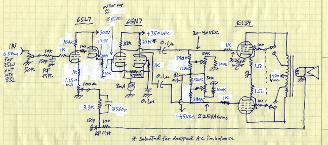
It's not until you draw up a circuit and crunch the numbers
that you can see what's wrong with it. The front-end 6SL7 topology was chosen
because it provides a nice port for global feedback, and because being single
ended it will generate a good sounding (natural) harmonic spectrum, with the
2nd harmonic being significantly higher than the 3rd, and a quick roll-off
of harmonic distortion products after that (as ideal as it gets). Also because
being a different topology than the second stage, it's more likely to have
a complimentary sound, and less likely to cause a buildup of any undesirable
artifacts that may be inherent with a given topology (spectrum signature).
With the 2nd half of the 6SL7 being used as a follower-buffer, the front end
can run very linear. The 6SL7 is already one of the most linear triodes out
there. Since I want to have only minimal feedback, and therefore not too much
open-loop gain, the cathode bias resistor is not bypassed.
Since it is direct coupled to the differential phase-splitter
second stage, no coupling cap is needed, but the bias of the front end triode
must be set just right to deliver 85-90 VDC to the grid of the 6SN7 diff amp,
since it could otherwise have a detrimental effect on the dynamic range (headroom)
of the differential amp output. In conjunction with the CCS (constant current
source) in the diff. amp stage, it determines the operating point of the plates
of the 6SN7 diff. amp. Since both the 6SL7 follower and the 6SN7 diff amp
are held way up high in voltage by the front end plate, they can both use
a CCS going to ground, rather than needing a negative power supply.
The resistive divider off the 6SL7 follower gives several benifits:
I can get rid of some gain (6dB) since I have more open loop gain (feedback)
than I wanted. It also gives me a DC level shift (from 175 volts down to 87
volts) that allows me to operate the front-end 6SL7 in a more linear way (with
its plate closer to half of a higher B+). It will also reduce front end noise
by 6dB. Even with this attenuator, I'm still stuck with more gain than I wanted.
The feedback control will have zero to about 20 dB range (less in triode mode).
I would have been happy with 10dB max feedback. When you turn down the feedback,
the gain of the circuit goes up higher than I wanted. The down side of these
resistors is that they need to be small to keep miller capacitance in check,
which means they will dissipate significant power, and draw enough current
that the current source (shown in dwg) would need to be replaced by them.
Not a big deal.
The biggest criticism of the differential middle stage (that
I know of) is that one section has miller-effect grid to plate capacitance,
and the other doesn't. Since the gain of this stage is only about 25, and
since Claus Byrith is using it with great success, I'm not necessarily worried
about it. I designed in an AC imbalance before I realized that the feedback
would un-do the imbalance, leaving less headroom and less spectral distortion
advantage.
To minimize the likelihood that the output stage will ever lose
bias (catastrophic) or have a significant variation of bias due to tube aging
or etc., I've put coupling caps after the diff amp, and used an output tube
bias topology that reduces output tube current flow in the event of
an intermittent bias pot, rather than letting it go full boar like virtually
all other designs. If the bias on the output tubes ever went to zero for any
reason, the tubes would turn on all the way, and this would likely cause major
damage to the output tubes and/or the output transformer. Not likely, but
possible.
Research has shown that capacitor distortion becomes significant
when you have very small signal levels, and/or when you are operating the
cap as a significantly resistive device, such as in a filter. In this case
neither is true, so the cap is not likely to cause any significant distortion.
The output stage will have very small cathode resistors for
setting bias (1 ohm), so the plate impedance stays as low as is practical
for minimal distortion and best damping of the speaker motor. The screen grids
can be switched for either ultralinear mode (35 watts) or triode mode (16
watts). Triode mode is more linear and because of the lower plate impedance
gives better damping to the speaker driver. Switching to triode mode will
also reduce the amount of feedback by about 6 dB.
Feedback would be adjustable from zero to about 15 dB (in ultralinear
mode). Since the entire circuit was carefully designed to be very linear,
it could run well with no feedback at all. Some feedback reduces gain variations
due to tube aging, and presents a more practical output impedance to the speaker.
Too much feedback will create excessive higher order distortion products,
and thereby a less desirable sound (tedious). Most very high-end amps seem
to favor about 4-10 dB of feedback. It depends on how reactive the speakers
are. Less feedback is generally better sounding if the speakers are minimally
reactive or resonant.
The reactive elements (coils and caps) in a typical passive
crossover are designed to see a zero ohm source impedance, and usually an
8-20 ohm driver impedance. If the speakers have passive crossovers in them,
a one ohm source impedance could throw off the calibration of the crossover
by more than 10%. Jim Fosgate puts a one pole passive crossover ahead of his
low and no feedback tubetype poweramps in his tri-amped system, perhaps for
this reason.
The feedback cap is selected for the best squarewave response.
Using different tube types in each place keeps any less desirable signature
artifacts from building up. All grids have 1Kohm anti-oscillation resistors
mounted right at the tube pins.
Notice the Rf filtering in the global negative feedback path.
It's to reduce Rf energy that is picked up out of the air by the speaker wires
acting as an antenna. Imagine what radio frequency energy would do to the
recirculating feedback situation... There's also an Rf filter at the input.
What?! You mean you don't have these in your amp?!!!
Still not convinced? Here's what Siegfried Linkwitz has
to say about this:
"Speaker cables can act as antennas in the AM frequency band and may
cause distortion in the output stage of a solid-state amplifier, if strong
radio frequency signals are present. In particular, the cable capacitance
in conjunction with the inductance of a driver voice coil may form a resonant
circuit for these frequencies. The resonance can be suppressed by placing
a series R-C circuit of 10 ohm/2 W and 0.33 uF/100 V across the cable terminals
at the speaker end. Coaxial interconnects with phono (RCA) plugs tend to
pick up radio frequencies in the FM band. The currents that are induced
in the cable shield must not be allowed to enter the inside of the coax.
This requires a very low resistance connection between the outer conductor
of the phono connector and the chassis (signal ground) of the equipment
that it plugs into. The continuity and low resistance of the shield is also
very important for hum and buzz currents, so that they will not induce a
voltage on the center conductor. The technical description for this is the
Transfer Impedance of the cable and connectors, which must be in the low
milli-ohm range. Unfortunately I have not seen this specification used by
the audio industry. An excellent description of the theory and treatment
of hum and buzz problems in equipment setups with mixed two and three prong
AC plugs is given in AN-004 by Jensen Transformers, Inc. I have not found
balanced interconnections to be necessary for the high level circuits past
the preamplifier. But sometimes it requires to experiment with AC outlets
in different locations to reduce to insignificant level the buzz that one
may hear with the ear close to the speaker cone. So, when choosing a coaxial
audio interconnect look for good mechanical construction, direct contact
between shield and connector, and well plated contact surfaces. I find what
is needed at Radio Shack. I solder speaker cables to terminal strips on
the speaker end and use dual in-line banana plugs on the amplifier end."
You can put Rf filtering in as I did, or you can pay over a thousand dollars
for a special braided speaker cable that I've been told may have antenna-effect
cancellation, or you can ignore this althogether and possibly have an amp
that is often in a state of slewing due to the feedback circuit trying to
react to energy at frequencies beyond its capability (almost guaranteed if
you have light dimmers in your house). As if slewing related distortion generation
isn't bad enough, as soon as Rf energy gets to a device that reacts non-linearly
to Rf energy, the non-linear device "detects" or AM demodulates
the energy (generates sum and difference frequencies), and splatters noise
all over the audio spectrum (and the rest of the spectrum) (the difference
frequencies will land in the audio frequency region).
Here's another one of my tenative/explorative designs:
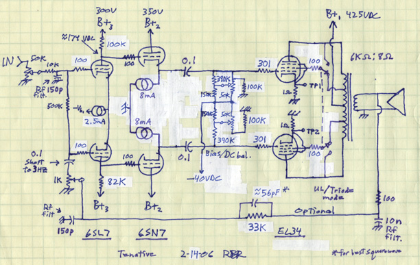
A symetrical drawing always looks so nice. Too bad it inherantly
generates odd harmonic distortion products but very little even. There is
a question of whether or not I should move the coupling caps upstream by one
stage to before the followers. If I don't see blocking distortion with
this topology, then it's a little cleaner this way. If I move the caps upstream,
then I've got to create a grid return path for the followers, which puts a
few more resistors in the signal path. Compared to blocking distortion, that
seems like a small price to pay. I can change that later if I need to.
Blocking distortion is where the tube is driven into
saturation during peaks to the point where grid current flows, which causes
a negative DC charge to accumulate on the coupling cap at the grid, relative
to the other side of the cap which is ultimately effectively connected
to the cathode of the tube in question. When the sinewave input signal directs
the tube back to the zero crossing, this charge causes it to get there too
soon by providing an additional negative bias. The tube stays in cutoff until
the DC on the cap can discharge, or be overcome by a bigger drive signal.
The shift in amplitude is one thing, but the delay that this can cause creates
substantial crossover distortion. This is a distortion which is relatively
unpleasant and is hard on speaker drivers due to its sharp corners. The Dynaco
Stereo 70 has this, but because of the huge imbalance in the source impedances
coming from the phase splitter, the crossover distortion actually rises up
the sinewave as you push the amp further and further into overdrive. This
may make it slightly less audible. It's been said that the only way to be
sure this will never happen is to drive the output tubes with interstage transformers
($90 + each) or drive them with direct coupled cathode followers (so I'm told),
or by making it impossible for the EL34's to be driven to within a volt of
zero bias somehow.
In the typical RC coupled circuit, it's best to use as small
a cap as is practical, and as big a grid stopper resistor as is practical
to reduce grid current flow during these times of overload (a bigger grid
stopper resistor will take away from phase margin at the high end, so be aware).
Here's part of an article published in Audio magazine in 1959 (the "golden
age")
by Norman H. Crowhurst:
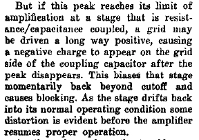
for the full article in pdf format, click here.
Phase Margin:
It's been said that the drive requirements for output tube miller
capacitance may be more demanding than is conventionally believed. Some people
feel that supersonic energy (20kHZ - 100kHZ) needs to be able to mix, and
be handled by the feedback system in a linear way, and because of that, it
is considered desirable to have more than enough drive capability in that
region of frequency (to well beyond 100kHZ), driving into the output tube
miller-C. Put another way, the open-loop bandwidth of the circuit should be
better than 100kHZ, and ideally be limited only by the output transformer
pole, so the rolloff rate will be one pole and therefore only have a max of
90 degrees of phase shift before the feedback loop gain goes below one. Any
more phase shift than that suggests instability (spurious oscillations and/or
slewing and/or ringing). Another issue is that the input signal should be
bandwidth limited to about 50-100kHZ, so that the signal itself never tells
the amp to do something it can't do competantly. In trying to handle energy
above 50kHZ, it will likely overdrive the tube or transistor that immediately
precedes the bandwidth limiting mechanism (stage), if there's any feedback.
That preceding stage will likely slew and/or clip. This is covered in more
detail below, as well as on my MusicBox calcs page (link below).
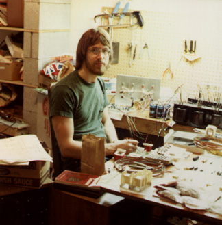
Matt Kamna building a class A transistor amp back in 1980.
BUT NOW
- FINALLY...
Here's my latest design (3-14-06), the one I'm actually building:
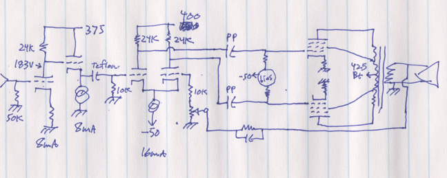
This is a concept drawing. I didn't bother to draw in the grid
stopper R's (all 1K), or the Triode/UltraLinear switch circ (same as above),
or the bias circuit (same as above). In the second stage 6SN7, one of the
24K ohm resistors got changed to 28K to strategically unbalance the drive
to the output stage just enough to give the better distortion spectrum shape
(2nd harmonic higher than 3rd). The front end tube is a 6F8G ST bottle (same
specs as a 6SN7 but has a grid cap and a cool shape), the differnentail phase-splitter
second stage tube is a 6SN7, and the output tubes are EL34's. The current
sources are 3 terminal T0-220 devices (IXYS brand, IXCP 10M45S). There are
several nice features here that may not be immediately apparent. I also later
changed the follower stage so it is no longer direct coupled to the front
end triode, so it is more accurately biased, and so less distorted.
The front end is a single-ended triode gain stage and a buffer
with no feedback of any kind, so the distortion spectrum shape will be the
most natural and best sounding you can get. The differential second stage
gives the needed phase splitting, plus an input port for semi-global negative
feedback, which is continuously variable from 0-14dB.
The cathode bias resistor in the front end isn't bypassed, because
I don't need or want that much open-loop gain, which later becomes feedback,
and to avoid the dielectic distortion of a large cap - probably an electrolytic.
Any distortion mechanism in the cathode or grid circuit of a tube stage gets
multiplied by the gain of the stage before being dumped into the signal path.
Having no bypass cap on the cathode resistor will cause the plate impedance
to go higher, which normally causes it's output to be too easily loaded down
by subsequent stages, thereby causing significant I.M. distortion (non-linearity).
With a follower buffer there, it shouldn't be a problem ( a hard-core purist
would put a current source in place of the resistor on the plate of the front
end triode - but then you have another can of worms - phase shift at supersonic
frequencies, slewing, etc.). It will have the characteristic high 2nd harmonic
(a good thing), and a fast and natural rolloff of the higher order harmonics
(nothing showing at -90dB down after the third harmonic), and minimal I.M.
products due to high linearity afforded by the choice of tube and the buffer.
Any "bloom", "delicacy" and "harmonic naturalness"
won't be damaged by feedback, a balanced topology or the presence of the electrolytic
cathode resistor bypass cap.
By adding the coupling cap after the follower, I get to run
the differential amplifier/phase splitter/driver with the grids as 0vdc. This
means I can direct-couple the feedback from the final output to the other
side of the diff amp (no coupling cap needed that would contribute to "motor
boating" instability due to phase shift at the low freqs).
Feedback is generally considered a potentially evil thing.
It can cause instability, slewing, generation of higher order harmonics, motorboating
oscillation, and apparently loss of "bloom and delicacy" especially
in the midrange and treble. It's also very arguable that feedback is needed
for the sake of taming the rather variable impedance and ringing of the substantially
reactive (as opposed to resistive) speaker transducer. The reactive nature
of a speaker driver causes substantially frequency-selective counter-electromotive
force generation (opposing current flow) , which plays tug-of-war with the
output stage, attempting to shift in time, depending on the frequency, the
feedback signal, as viewed by the diff. pair. The stage that receives this
feedback (the diff. pair) then tries to use it to correct what is happening
at the output and may be pushed into slewing or clipping (overdrive) by trying
to do something that can't be done, which will increase generation of higher
order distortion products substantially.
The hard-core tube amp designers like Jim Fosgate, Claus Byrith,
Manley amps and many others seem to favor about 8dB of feedback, which is
much less than the historical convention (25+ dB)and quite a bit less than
is typical of most solid-state stuff (50-120dB). They claim that if you don't
over use feedback, you get the necessary damping of the speaker transducer,
without the loss of sound quality and the instability that is substantially
more likely with higher amounts of feedback.
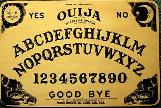

The proper tool for desgning feedback.
A Ouija board is useless without the Planchette.
Even with about 10 op-amps still in the signal path (preamp
and holographic generator), the sound seems significantly improved by using
this tube poweramp rather than a Hafler 220, which I've always thought of
as a relatively good FET output transistor amp. This makes me think that handling
the reactance of the speaker motor is one of the more significant weak links
of many systems.
I'll have variable feedback, from 0dB to about 14dB. Very significant
is that I'm taking the feedback to the driver stage rather than the front
end. When you take feedback all the way back to the front end (much more conventional),
the feedback signal tells the front end to tell the driver stage to try and
force the output stage to keep up with the input stage directive. Lotta cooks
in da kitchen. When the output stage gets lazy at high frequencies, the driver
stage will often be over-driven by the front end (effective diff. amp) because
of it's 20+ dB of gain, and is thereby likely to slew and/or clip . This is
more likely to happen at supersonic frequencies where phase shift will exist
due to the various high-end poles. Things like digital noise, RF noise, and
any energy in the program material above 20kHZ can activate this potentially
ugly distortion mechanism which can generate I.M. products that will be at
audio frequencies (the difference frequencies). The output stage is usually
the "dominant pole" or first pole, usually due to transformer bandwidth
(as in this case). When super sonic energy comes through, you want to be able
to deal with it elegantly to avoid slewing, instability or overdriving any
where in the feedback loop. By having the feedback go back to the driver stage
instead of the front end, these potential problems are substantially reduced.
Now it's the driver stage only that is telling the output stage directly to
hurry up, without the probability of being overdriven by the gain of the front
end, and with fewer reactive componenets in the feedback loop path. There
are only two highpass poles (the transformer and the coupling caps on the
grids of the EL34's), and the low pass poles are well staggered for good stability
at the high frequency end of the spectrum.
Stability Theory (phase margin continued):
What does "well staggered" mean? Any amp circuit will
have many poles at the high frequency end (and low frequency end), each of
which will contribute it's own phase shift of up to 90 degrees per pole (45
degrees per pole at the 3dB down frequency) as it rolls off the signal amplitude
with its lowpass effect. The phaseshift gets significant long before the amplitude
rolls off significantly. To use feedback without oscillation due to phase
shift, you have to have one "dominant" or first pole roll off the
amplitude of the feedback loop to below one, before the composite phase shift
from all significant poles adds up to anywhere near 180 degrees. Since the
feedback is 180 degrees out of phase at midband frequencies (as it should
be), another shift of 180 causes the feedback to be positive. Anything past
270 degrees would be pushing your luck. In the real world, there may be other
things that are reactive, such as a speaker transducer which may cause additional
phaseshift at certain frequencies more than others, or the output transformer
may be both inductive and capacitive at roughly the same area of frequency,
thereby causing a 2 pole rolloff charactoristic (Matt says it is). The ideal
situation is where you have one "dominant pole" at say 50kHZ, and
then no other poles until you are way higher in frequency. In the real world,
this isn't always easy to achieve (hence all the unstable and harsh amps out
there - especially in the early days when they didn't have a good understanding
of this).
In this amp, the next pole beyond the "dominant" or
first pole of about 50kHZ (caused by the transformer) is at about 316kHZ (miller
effect of EL34's driven from 6SN7 w. 24k plate resistor), and then the next
pole after that; the miller effect pole of the diff. amp is above 2mHZ . Anywhere
you can push a pole, other than the "dominant" or first pole, higher
in frequency, you do it because it buys you stability; a bigger phase margin.
Sometimes you pull down in frequency the "dominant" pole (if possible),
so it can roll off the loop gain to below one before the next pole(s) can
contribute a lot of phase shift. The cap across the feedback resistor (which
I didn't need) tries to effectively neutralize the phase shift of whatever
poles are at play, in a certain area of frequency, to reduce ringing, which
is evidence of a disappearing phase margin. There are always tradeoffs, and
this is one of the most important. Arguably THE most important. If you want
to be thorough, you could model your poles in a SPICE analysis program and
see exactly how much theoretical phase shift you have at the frequency where
the feedback loop gain goes below one (there's free "5SPICE" software
on web). I just use the Ouija board and planchette. A similar kind of thing
happens at the low frequency end, which can cause "motorboating".
"Well staggered" means that the pole that is rolling off the feedback
loop gain to below one is distant in frequency from any other poles, so phase
shift doesn't cause instability. (See my SPICE phase margin model and analysis
graph on my calcs page - port below)
Harmonic Spectrum:
Although any balanced circuit, such as a differential pair or
a push-pull output section, will generate odd harmonic distortion products,
it will generate very little even harmonic distortion products (depending
on how precisely balanced it is), it won't cancel even harmonics that are
already in the signal, and are generated outside of the feedback loop. Unbalancing
the AC drive to a push-pull pair brings back the even harmonics, but then
the arguably necessary feedback greatly compromises the benifit of the imbalance
by undoing it to some degree. Keeping the front-end single-ended stage outside
of the feedback loop will contribute to the better distortion spectrum shape,
input to output. When feedback is increased, the generation of higher order
harmonic distortion products is the result (along with better numbers on the
Audio Precision distortion meter, looking at one mid-band frequency), but
you may need to have some feedback to handle the reactive nature of
the speaker motor. This is a key tradeoff. Too much drive imbalance will increase
I.M. distortion too much.
Enough Gain?
The gain of the front end stage with the buffer is approx. 10.2
or 20.2dB. The gain of the differential/phasesplitter/driver stage is about
14.9 or 23.5dB (I need to verify that with the actual circuit since I couldn't
find a gain formula for differential operation that was convincingly complete).
The gain of the output stage operated in triode mode including the transformer
is -3.8 or -11.6dB (built and measured). With 8dB of feedback, the driver/output
section will have very little voltage gain (if any) due to its relatively
low open loop gain (it will operate mostly as a current amplifier), but will
handle the reactance of the speaker load better than most. The front end gets
the overall input to output gain back to about right.
Priorities:
My highest priorities here were a relatively natural harmonic
distortion spectrum with minimal generation of higher order harmonics, and
minimal likelihood of slewing, I.M. product generation and instability due
to the arguably necessary feedback which can help handle and speaker reactance
by presenting a lower output impedance to them.
The front end circuit gives me the input to output gain I want
with a very nice and natural distortion spectrum. It has a 2nd harmonic that
is bigger than the 3rd, and a very fast rolloff of the higher order harmonics.
The relatively local semi-global "loop feedback" in the output section
gives the needed damping of speaker reactance, with minimal likelihood of
generating high order harmonics, slewing or instability. With the triode-mode/ultralinear-mode
switch and the variable feedback control, it can be further optimized for
a given speaker reactance. This is currently my favorite topology. This is
what I'm building.
Construction:
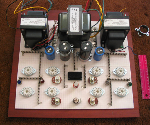
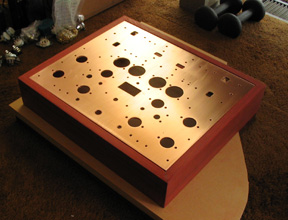
This is one of my favorite parts of the process. I laid out
the parts on graph paper that was taped to the 1/8 inch thick copper chassis
plate, while visualizing signal flow and potential problems with high impedance
and such. Then I marked up the paper with a pencil, then used the hammer and
center punch to prep the chassis plate for drilling, using the marked up graph
paper as the template.
Two months later:
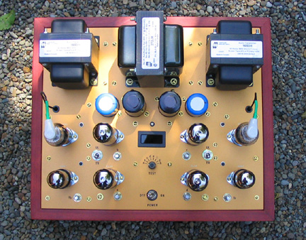
The grid caps on the 6F8G input tubes have a 1Kohm 3 watt metal-oxide
anti-oscillation resistor under heat shrink at the cap, and a shielded cable
with only one end grounded. They have no DC on them. There's a built in digital
meter and gold contact selector switch for checking/setting bias of each output
tube. Each tube is independantly adjusted. The Triode/Ultralinear switches
also have gold contacts since they will be dealing with relatively small currents
(maybe not that small - but not a good place for a weak connection). And then
there's the feedback pots. Zero to about 14dB.
The grid cap has been called "problematic" (the glue
holding it on can break loose), it adds some hum (because of the long wire
on such a high impedance point), and you've got to put the grid stopper resistor
right at the cap for it to be effective, but they look so cool I just had
to have it if I could.
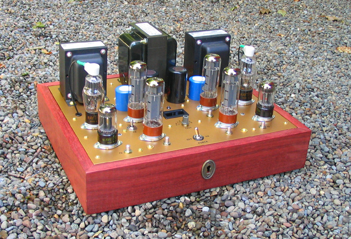
I call it The Musicbox. In this picture it's virtually
done, including the keyhole where you wind it up.
This amp tries to be the best possible version of a Dynaco Stereo
70, based on what we know today about tube amp design, within reasonable practical
considerations. This is my idea of the best set of tradeoffs on the bottom
line. The only thing it really has in common with the Dyna ST70 is the approximate
power output and the EL34's. Same market nitch sort of.
Transformers : Some will say that the Hammond transformers
aren't very esoteric. I've heard arguments on both sides. A lower pole actually
means more distance in frequency from the next pole up (assuming the transformer
will be the "dominant" or first pole, which it very probably will
have to be), which means better stability (larger phase margin). Hammond claims
that these trannys are only 1dB down at 30kHZ. One guy at a recent, relatively
valid "transformer tasting" session said he heard no difference
at all between several transformers being tested, which included the Hammonds
as well as some very esoteric ones. Matt Kamna had built up the test rig.
However, having said all that, in my amp the low end distortion
turned out to be very high. At 50HZ I would guess from looking at the sinewave
into a resistor, that the distortion was about 5%, and it gets a lot worse
down at 20HZ. Tests have shown that distortion in the bass is less audible
than any other frequency area, and many woofers are in fact very distorted
down there. Since I'm just using this amp for 50HZ and above, I probably won't
bother to spend hundreds on better transformers, but if I was using it wideband,
I probably would. DeHavilland aparently uses the big heavy Electro-Print brand
transformers that are apparently designed and produced in Las Vegas.
Back to the important stuff:
The keyhole will eventually have either an infinite mirror with
tiny white lights or a transmission projection hologram backlit by a lasor
diode (same one used to make the hologram). The holograms could be changable.

It's mostly done here. The meter circuit needed it's own power
supply (lower left) so it's input could be referenced to Gnd of B+ (the filiment
supply is floated at around +90vdc to reduce hum and keep the amp from exceeding
the filiment to cathode voltage spec., and the bias supply is negative relative
to B+ gnd. so neither were usable for this application).
Each stage has its own 0.1uF polypropylene power supply bypass
cap (the orange caps in above pic) and ground return wire to the "star
center" at the main filter cap (for best wideband stability). You can
see the small toroidal transformer (blue) for the negative supply mounted
right under the power transformer. The B+ HEXFREDs are just to the right of
it, with their .01uF 3kV ceramic caps right across them (for noise reduction).
There's a total of five power supplies; three off the main tranny (B+ and
two for filiments), one off the toroid and then the meter supply.
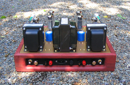
The rear panel.
Floating Input and output jacks (each with separate ground wires
going to star center circuit ground at the main B+ filter cap), IEC AC connector,
primary fuse and input level controls are all on the rear panel. The knobs
are replacements for a 1960's Marshall guitar amp. They're real nice, and
they're real cheap (at Antique Electronics in AZ).
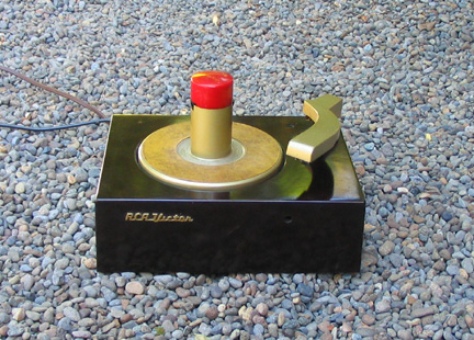
When it's all done, I'll check it with my state-of-the-art
turntable.
I hope to have a natural and fast roll-off distortion spectrum
like this (This is a single ended triode):

The noise floor on this HP spectrum analyzer is 85 dB down.
The peak that just touches the top line of the graticule is the fundamental.
Power Supplies:
Many people are designing power supplies that are very elablorate.
In doing this, they may be causing problems. The amplifier circuit needs to
see zero ohms impedance for AC from below the lowest frequency to be reproduced
( 1 or 2 HZ is what I go for) to well above 100kHZ. Otherwise, you piss away
your phase margin. If the impedance rises at the low end, there will be an
attenuation of gain; not necessarily a big deal, and possible "motorboating"
instability due to phaseshift. It's easy enough to get big caps these days
and bypass them with a high end plastic dielectric caps for a better high
frequency impedance curve. If the impedance of the power supply as viewed
by the amplifier circuit rises at the high end, there can be instability there,
especially if feedback is used.
Many people think a choke is a good idea. I did a bunch of choke
supply modellings with the Jim Duncan power supply program and found that
if the capacitance on the output of the choke is higher than about 20 uF (with
a 5 henry choke), the supply filter causes negative current flow, which I'm
not sure is a good thing. It suggests a tendency to ring at some frequency.
With a 500uF cap, the resonant peak was off the graph. Not a good thing at
all. I wanted to use caps that are much bigger after the choke, so the amplifier
would see zero ohms to very low frequencies AND very high frequencies. I've
decided not to use a choke at all. They were apparently useful in the days
when the biggest caps available at 500 volts were 20-40 uF.
I'm using 500uF 500 volt caps made by JJ. One right at the B+
diodes and one 10 ohms away from it, for my main B+. There's additional heavy
filtering for the diff. stage and front end circuit. I've of coarse got 0.1uF
high grade (polypropylene) caps across each circuit section out in the circuit
physically, each with separate ground returns to the ground "star center",
to insure a zero ohm impedance as viewed by the amplifier circuit to very
high frequencies with very low distortion.
The high-V diodes (HEXFREDs) are high speed low noise, shunted
with 0.01uF 3kV ceramic caps. I'm rectifying the five volt winding to get
DC for the filiments of the front end tubes (to reduce hum). The output and
diff amp tubes have AC on their filiments. All tube filaments will be floated
at about 90 volts relative to circuit ground, to insure that electrons will
never be attracted to the cathode from the filiment (to reduce hum and noise),
and so the cathode to heater spec in the follower stage won't be exceeded
at quiesence (people ignore this spec all the time in the guitar industry,
but maybe not a good idea). This floater divider acts as the bleeder resistor
for the B+ caps. All ground connections return to a "star-center"
at the negative terminal of the main filter caps. A ground switch (not in
pics) connects the circuit ground to the earth ground (center pin of the AC
plug), which reduces hum substantially (depending on the situation).
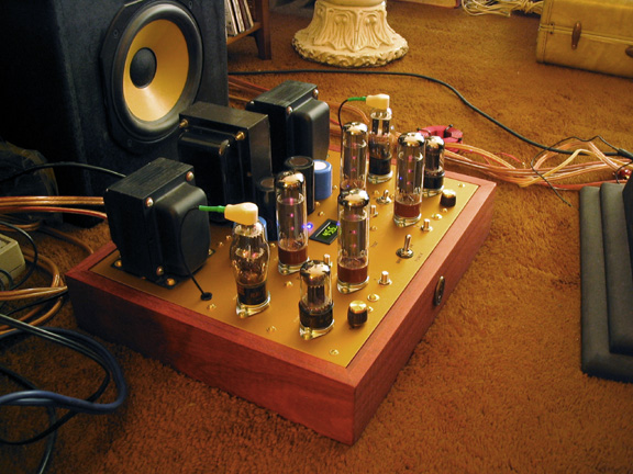
First Listening test.
"Tube Friendly Speakers":
While I'm thinking of it, if you want speakers that are "Tube
Friendly", you want a 2 or 3 way system that has the simplest possible
one-pole crossover with no notch filters to accomodate hard cone (kevlar,
ceramic, aluminum, etc.) drivers, or other "fancy" EQ. This is because
of the high output impedance of a low or medium feedback tube amp output stage.The
fancier and/or higher order (2 pole, 3 pole) crossover will be thrown out
of calibration much more, by the typically 1-8 ohm output impedance of a high-end
tube amp. If the reactive components of the crossover (coils and caps) were
designed to see the 8 ohms of the driver in series with the approx. 100 milliohms
source impedance of the typical transistor power amp (they are all designed
that way), then adding in a say 2 ohm tube circuit output impedance will change
the crossover frequencies by roughly 20%. Since the two drivers in most speakers
are not of the same impedance, at the crossover frequency (14 ohms for the
five inch midrange drivers vs. 7 ohms for the ribbon tweeter in my case),
they each shift by different amounts (in the same direction). With one-pole,
the shift isn't likely to be too damaging. With 2 pole filters, the frequency
shift will be at least double, plus the curve shape is now thrown off.
The more you turn down the feedback in the tube amp, the higher the output
impedance of the amp will go. It will allow the speaker drivers to resonate
(usually around 70HZ with five inch drivers), and will un-calibrate the crossovers.
Low feedback is a big plus in many ways. This is not one of them. This
is the tradeoff. When you have a notch filter that is making a "high
resolution" hard cone driver be "usable", you run the risk
of moving the notch completely off of the cone resonance altogether when you
put in a tube amp that adds 2-8 ohms of source impedance. Drivers with cones
that are just hard enough but no harder, seem to be the way to go. Going too
hard seems to cause pretty severe conductive, and thereby radiated resonances,
and cone breakup distortions at the high frequency end, from what I've seen.
The good drivers will have a smooth enough rolloff that you can relatively
successfully use a very simple one-pole crossover. One that's most forgiving.
See my Aurium Waveguide speaker project page.
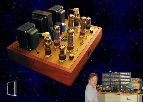
I like to play with Photoshop.

I think she likes it.
For full details on the schematic and
circuit calculations, click here.
For test results of finished amp, click
here.
ETC:
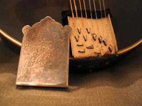
In the picture below you can see how they've actually "tuned"
the harmonic effects of the strings beyond the bridge on a very old Gibson
mandolin.
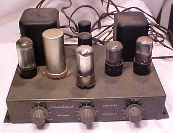
Below is the amp my dad built and had when I was around three
years old. I would tilt it up and see the innerds. One of my first fascinations.
It might be the very first Heathkit amp they ever made. I found this picture
on ebay.
More later..
Notes from my earlier research:
What I've been told:
-
There's a cult following that consider Class A single-ended
directly-heated no-feedback triodes amps the best sounding. They mutter
things like "micro-dynamics", and "natural harmonic spectrum
with quick rolloff", and "soggy or wooly bass" (which is
a typical artifact of low damping factor).
- People say that tubes don't sound as good when they are paralleled.
- When there's no feedback, using a giant triode (GM-70 for ex.) with its
lower rP, will give a lower output impedance (better damping factor).
- Pentodes wired to operate in triode modes aren't as good as a real triodes.
-
Pentodes in ultralinear mode sound better than in regular
pentode mode.
- Output tubes can be run in class A2, which reduces the audibility of clipping
and increases output power somewhat, but this means they draw grid current
for part of the cycle when driven hard, and it's therefore very important
that the driver can handle the drastic increase in loading on it's plate.
This is also harder on the tube (shorter tube life).
- In class A2, when the grid draws current, the coupling cap on the grid will
suddenly be looking at a much lower impedance and if not sized for that will
cause a major reduction of bass, plus the possibility of blocking distortion.
Better to drive a class A2 or AB2 output stage with an interstage transformer
(or a follower).
- Push-pull and other balanced topologies produce odd harmonic distortion
products, but not even..
- Negative feedback reduces distortion and tightens damping factor by reducing
amplifier output impedance, but is likely to cause the generation of higher
order harmonics, which recirculate endlessly in the feedback loop, generating
new low-level I.M. and harmonic distortion products all over the spectrum
each time around the loop. This may be why low or no feedback circuits have
been more popular lately, despite the cost to the damping factor.
- Damping of the CEMF from the speaker is audible. It's been said that no
feedback provides too little damping . Not only are resonance's in the speaker
exaggerated by the load impedance variation effect on amplifier gain, but
a passive crossover in the speaker system is very typically designed assuming
a zero ohm source impedance, and now you're adding 1-4 ohms to what was an
8-20 ohm circuit as seen by the reactive elements. You thereby substantially
un-calibrate the crossover.
- Blocking distortion, which is a serious overdrive problem in any capacitive-coupled
push-pull output stage, can only be eradicated by driving that stage with
an interstage transformer instead of capacitors. This is a notch-like distortion
that occurs in the crossover region when the circuit is significantly overdriven.
Very ugly. Go to the Aiken audio website for more info.
- Most tube fanatics claim to be able to hear the difference between the various
capacitor dielectrics, and avoid them altogether when they can. Apparently
the oil and paper or teflon are the best. Polystyrene and polypropylene are
real good too.
- Although single ended (SE) output topologies without feedback have more
2nd harmonic distortion than 3rd, which is good, and the dropoff of harmonic
distortion products is much quicker (fewer higher order harmonics, which is
particularly good). This can be largely a consequence of the circuit being
non-linear, or more specifically, asymmetric, which suggests higher I.M. distortion
(real bad). This can allegedly be reduced by having adjacent stages provide
the opposite non-linearity (an early stage that inverts could create a non-linearity
that will to some degree allegedly cancel with the output stage non-linearity).
- It may be possible to get a more natural and better sounding rolloff of
harmonic distortion products in a push-pull topology by turning down the AC
gain on one of the output tubes, while maintaining DC balance. This may only
work when there's no global feedback which would un-do the imbalance..
- Each tube has a signature sound that is such that it may compliment the
signature sound of certain other tubes.
- Putting too many of the same tube in a given signal path can bring out the
worse of that tubes signature sound.
- Larger plates sound better.
- Round plates may sound better.
- The 6SL7 and 6SN7 are two of the most linear low power triodes. Significantly
more linear than the 12AX7.
- Claus Byrith says the output transformer is by far the most critical circuit
element. He is very happy with the Lundahl transformers.
- One guy who attended an output transformer comparison session with Matt
Kamna said he couldn't hear any difference at all between the various transformers.
- and a bunch of other stuff.

What I am learning:
- Pentodes have high and non-linear plate resistance so feedback is said to
be necessary (26dB was suggested). Triodes can usually get away with not having
feedback (or at least a lot less) since their plate resistance is substantially
lower and more linear. This includes pentodes wired to operate as triodes.
- Triodes have substantial miller effect, so when multiple triodes are paralleled
the input capacitance becomes difficult to drive.
- Push-pull output topologies have distortion harmonics that are of significant
amplitude further out in frequency, relative to single ended topologies, even
without feedback.
- A push-pull output topology can have blocking distortion when substantially
overdriven unless the output stage is driven by an interstage transformer,
or low impedance followers. These interstage transformers cost $90 each (Lundahl
1660 or 1671 for ex.).
- The primary impedance of an output transformer when properly loaded on its
secondary should be 4-6 times higher than the triode output tubes plate resistance,
generally. Less means more power and higher distortion. More means the opposite.
- If you have a push-pull output stage, half the end-to-end primary impedance
is the number to design for if you are running class A. If you run class B
(or AB that is rarely A), then the primary rating will be twice as heavy a
load on each plate as when class A. This is because the presence of the second
tube is effectively a positive feedback from the point of view of the plate
of the first tube, thereby cutting its perceived load in half. If you design
these impedance's based on class A, but bias the stage such that near clipping
the tubes go out of class A into class AB, there may be a compressor/limiter
effect due to the effective doubling of the loading by the transformer when
one of the tubes goes into cutoff. The stored energy in the transformer core
may reduce this effect.
- Two tubes in class AB push-pull will give four times the power of a single
tube. Paralleling two tubes class A single ended will give twice the power
of a single tube.
- If you are going to run the output stage in class AB2 or A2, that means
that grid current will be drawn on the saturation half cycle. It is common
for engineers to forget to make their driver stages capable of handling this
abruptly dropping impedance elegantly. There is likely to be both waveshape
distortion and bass cut, unless these have been accounted for in the design.
When done right, A2 gives significantly more power. It's also harder on the
tubes.
- When you parallel on additional SE output tubes, power doesn't increase.
Ability to drive a lower primary impedance on the output transformer doubles.
The transformer primary then needs to be readjusted to take advantage of this,
if more power was the goal. Halving the plate resistance allows you to half
the primary impedance, which will in turn approximately double the output
power with about the same distortion.
- When there is a cathode bias resistor, it is generally wise to fully bypass
it with a capacitor because the plate resistance of the tube will go up substantially
when such a resistor isn't bypassed. Unbypassed cathode resistor times stage
gain equals resistance that gets added to the plate resistance. High plate
resistance means variations in gain and damping. The conventional thought
that leaving this resistance unbypassed is a form of local negative feedback,
is not the whole story. If you changed this capacitor from one dielectric
type to another, the difference in sound may be due to the slight difference
in capacitance, or the dielectric distortion characteristic, which apparently
gets amplified by the stage gain.
- If an amp has good harmonic distortion specs but bad I.M. distortion specs,
single instruments will sound a lot better than choruses and orchestral music.
- Most affordable SE amps are said to sound "beautiful", but only
put out a few watts at 5% distortion.
- SE output transformers are physically significantly bigger than push-pull
transformers of equivalent power ratings, and the selection is more limited.
A transformer must have a gap, and apparently a bigger core, to be compatible
with SE designs (so the core won't saturate nearly as soon).
- Many of the most linear tubes ever made were very early designs, such as
the 45, the 2A3, the 85, the 6J5, the 300B, 6SL7, 6SN7.
- When filament currents add up to more than any of the affordable Hammond
power transformers can handle, you can rectify the 5 volt winding, and use
that for the heaters of the front end tubes. Now the 6.3VAC winding only heats
the output tubes. In both cases, series resistors are recommended for getting
the voltage to be exactly 6.3 (being off >10% in either direction will
shorten tube life significantly).
- Differential and class A push-pull topologies have inherently much
better powersupply hum and noise rejection, and show the power supply a much
more constant load. Too bad they kill the second harmonic distortion product.
The second harmonic is the same note as the fundamental, but one octave higher.
Often considered more of an enhancement than a distortion.
- If the AC balance is off in a symetrical circuit, you get some even harmonic
distortion products.
- If the DC balance is off a little bit, you may get better microdynamics
(linearity at very small signal levels) because the transformer core will
be biased into a more linear region at quiesence.
- One of the reasons tubes sound better than transistors is because of the
loose tolerances of tubes. This means better linearity at the microvolt level
since the output transformer will have some DC offset at quiesence,
and a harmonic distortion spectrum that will be more natural because of sloppy
balance of gain.
- Another reason tubes sound better than transistors is because of the reduced
need for feedback, and thereby open loop gain. The "dominant" pole
doesn't have nearly as far to go in frequency with its rolloff, to get the
feedback loop gain under one. It gets the job done way before a high open
loop gain circuit would. This means more phase margin, better stability, and
more resilience when dealing with the reactance of the speaker motors.
- and a bunch of other stuff.

Neurons - We have about 12-100 billion of these in our
heads (depending on drug usage and solder fumes). They gossip and daydream while
we sleep (and when we're awake). If we pose a question just before we go to
sleep (so they're not constantly interupted), they will research it and develop
answers, which they may or may not share with us when we wake up. The quality
of the answers will be a function of our past experiences (our thoughts, beliefs,
perspectives); particularly the self honesty and the accuracy of what we've
chosen to believe in our past. Edison took advantage of this function regularly.
Questions still to be answered:
- The EL34 is a pentode with a spec'd plate resistance of 15Kohms. I wonder
what rP is when wired in triode mode? I've read that it's below 2kohms.
- If wiring a pentode for triode mode reduces the plate impedance rather substantially,
then why do many engineers say that the appropriate transformer primary impedance
now needs to be higher than when the tube was operated as a pentode?
- Can the class of operation be switched without a need for a different primary
output transformer impedance?
- Is the 50-60% loss of output power due to switching from pentode mode to
triode mode because of the mismatch of rP to the output transformer primary
impedance?
- What's the recommended ratio of impedance between a "true" push-pull
tiode plate and its output transformer primary?
- Do tubes last longer when the filaments are driven with AC?
- Where can I get a job fixing and building tube amps?
- Where can I get one of these?
Or one of these, what the hell...


