(c) 2016 Robert B. Richards, All rights reserved internationally.

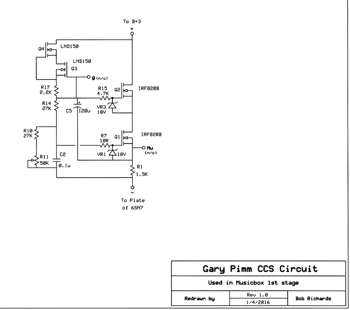
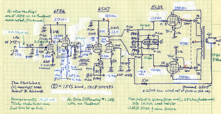
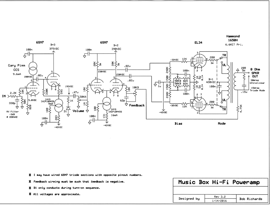
The follower has been modified since I wrote everything below, so there may be a few minor things that aren't talked about. The follower used to be direct coupled to the front end triode, but I found out that a follower biased that way generates an asymetric distortion, so I put in the cap, and set up the follower to be self biasing in a way that is more acurate and consistent over the swing of the signal. I also put a bigger resistor in between the 500uF caps in the power supply, which caused a small loss in B+ and a bigger loss in max power out. It would have been nice if the power transformer put out another 50-100 volts, but those transformers cost a lot more so... With efficient speakers like my Aurium Waveguides (96dB/meter/watt), 30 watts goes pretty far.
The 5K resistors and diodes are there so the current sources will have an idling current while the tubes warm up and start to conduct, at which point the top of the current source will rise to the bias voltage of about 5 volts, which will turn off the diodes, thereby unhooking the idler circuit. If you don't have this idler current, the current source will effectively hook the node (cathode of the 6F8G follower stage in this case) to the negative supply, which couples ripple of that supply directly into the signal path causing a significant amount of hum for a second or two while the unit is warming up. Apparently the 6SN7 and the EL34's start to conduct before the 6F8G by about one second.
The high-pass cap (50HZ) is after the front end stage, feeding the Input Level control.
The 62pF mica cap to ground at the wiper of the feedback pot is to cancel any Rf energy that might come in from the speaker wire acting as an antenna at Rf frequencies.
I want to drive an 8 ohm speaker from 50 HZ on up, with about 35 watts in ultra-linear mode, and about 16 watts rms in triode mode. I'd like to achieve full output with about 1Vrms at the input. When switching to ultra-linear mode, the gain of the EL34/transformer section will go up about 6dB, and the amount of feedback will go up because of that, by that amount. Since triode mode requires a larger signal level on its grids to achieve it's full output potential (the worse case in the gain calculations) , the following calculations will be based on triode mode.
P = E2/R ; E = (PR)1/2 ; E = (16 watts * 8 ohms)1/2 = 11.3 volts rms across an 8 ohm load.
Gain required input to output = 11.3V / 1V = 11.3, or dB = 20 log (Av) = 21.1dB.
Engineers will recognize that phrase. The voltage ratio of the output transformer is the square root of its impedance ratio. The impedance ratio of the Hammond 1650H tranny is 6600ohms centertapped / 8ohms = 825. The square root of that is 28.7. Since each EL34 drives half of the primary, the ratio to each tube will be half that, which is 14.4 . So 11Vrms (requirement on secondary for 16 watts rms out) * 14.4 (transformer loss) = voltage swing on plate of EL34 to get full power out = 158.4 Vrms or 224 volts peak. This means B+ needs to be 450VDC (twice the peak voltage plus minimal amount that is dropped on the DCR of the tranny).
Required signal on the grid of the EL34 = 224Vpk (max requirement for full power out) / 7.8 (actual measured AV of EL34 in this application) = 28.72Vpk per tube. This should be no problem at all for the driver stage to handle. This drive requirement may be less when in ultra-linear mode.
Gain of EL34 and transformer combined: 11volts rms / 20.3 Vrms (per side) = 0.542 = -5.32 dB theoretical.
Actual gain measured on bench was: 7.8 (EL34) * -30.2 (XFMR) = 17.8dB - 29.6dB = -11.8 or -3.8dB .
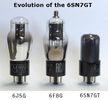
The 6F8G is the same as the 6SN7 (same PD, rP, gm and mu), but in an ST bottle with a grid cap. The 6J5 is a single triode version in an ST bottle with no grid cap. The 6SN7, although out of production, is more available than the 6F8G. I however like the look of the ST bottle shape and the grid cap. I'm a fool for nostalgia. My input tube will be a 6F8G, and the diff. amp will be a regular 6SN7. These tubes have different pinouts.
The tri-curve graph shows that 7-12 mA is optimal for this tube. In this front-end stage I will choose 8 mA. The tradeoff here is tube life against linearity. At 8mA, the tube is most of the way to optimum as can be seen in the tri-curve graph.
PD = 8ma * 188VDC = 1.5 watts, well under the 5 watt maximum spec. for the tube, but equal power will also be dissipated by the plate resistor at quiesence, so this resistor will need to be rated at 5 watts.
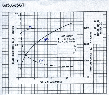
This graph should exist for every tube. I'm told they are rare.
With a power supply of 375VDC, to set the plate at half of that at quiesence (for maximum linearity and dynamic range), We divide (375/2) / 8mA (chosen from above graph) = 23.4 Kohms, or 24K (standard value) for the plate load resistor RL. The theoretical quiescent plate voltage will be around 1/2 of 375, or 188VDC, if the bias resistor is set for 8mA at quiesence.
Going to the characteristic curve graph (plate current vs. plate volts) of the 6J5 (single triode version of same tube), we draw a load line that goes from 375VDC / 24Kohms = 15.6mA (max current potential) on the Y axis to 375VDC (max voltage potential) on the X axis (see below).
By marking the intersection of that line with the plate voltage we hope to have at quiesence (188VDC), that same point when carried to the Yaxis will show the quiescent current, and the plotted curve under it shows what the bias will need to be. Then we can calculate the cathode bias resistor.
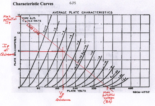
According to the graph, 5.0 volts looks like a good number for the bias voltage. An input level of 1-2 volts will have no problem being clean. If the input was going to be over 4 volts, then it may cause grid current to flow, which is harder on the tube and causes a severe collapse of grid impedance, and a huge shift of any poles that are dependent on that impedance. Also potential blocking distortion.
RK (cathode resistor) = 5.0VDC / 8mA = 625 ohms or 620 ohms (nearest standard value).
Gain of 6F8G without cathode bypass cap = mu * RL / rP + RL + (RK (unbypassed) * mu + 1)
= 30 (from tri-graph) (24KRL) / 8K (from tri-curve graph) + 24KRL + (620ohm * 31) = 14.1 or 23dB.
So the front end alone gives us all the gain we need from input to output (which was 21.1dB). Therefore, all gain in the output section (6SN7 phase splitter, EL34's and output transformer) can be used for negative feedback, without causing an input to output gain problem. The output section will be a current amplifier and a reactance handler.
Miller effect: is where the grid to plate capacitance of a tube gets multiplied by the stage gain, from the point of view of the driving electronics. This is because the grid and plate are out of phase with each other by 180 degrees.
The miller effect capacitance on the grid of the 6F8G input tube will be 14.1(stage gain) * 4pF(from spec sheet) = 56pF(actual).
Pole 6F8G = 1 / 2 * pie * 56pF * 12Kohms (input pot midranged for worse case) = 236 kHZ. This, in conjunction with the Rf filter at the input, will indirectly limit how fast the feedback loop will be told to try and correct the slowness of the output transformer.
The other section of the 6F8G will be used as a cathode-follower buffer, direct coupled to the plate of the input stage.
The output impedance of the follower will be: rP / mu + 1 = 8K / 31 = 258 ohms. This will have an easy time driving the miller capacitance of the differential phase splitter to follow. It's 8mA current will be set by a 3 terminal current source between its cathode and ground.
The current source ( IXYS IXCP-10M45S) will need to dissipate 193V (V plate + V bias) * 8mA = 1.54 watts. The T0-220 package is bolted to the copper chassis plate. The series resistor value is taken from a graph on its spec sheet (360 ohm). 8Ma * 360ohms = 2.88 volts. 2.88V * 8mA = .02 watts actual PD.
Cathode Follower Gain:
Formula = mu (RK) / (rP + mu (RK)
The load of the subsequent stage will be paralleled on to RK for full accuracy.
= 30 * 10Kohm (next stage) / 8K + (30 * 10Kohms) = 0.97
Referring to the same "Tri-curve" above, a good place to operate the 6SN7's is at 8mA per section. Below that causes substantial deterioration of quality as can be seen in the "Tri-Graph" above. Above that shortens the life of the tube.
The current source will be independantly set to 16mA (since it feeds both sections), and will dissipate 50V * 16mA = 0.8 watts.
The plate resistors necessary to drop about half of the supply voltage of 390VDC will be:
(390 / 2) / 8mA (per triode) = 24.4Kohms, or just 24K (standard value).
PD = 195VDC * 8mA = 1.56 watts. Well below the max PD spec for the tube, but these resistors will need to be rated at 5 watts.
Gain:
Each cathode is looking at the other cathode (the current source is effectively infinite resistance). The gm of each section is 2600umhos (384.6 ohms). Therefore the cathode resistance is 385 + 385 or about 770ohms (according to Steve Bench I think). This is the closest I could come to finding a believable gain formula for this exact topology.
Stage gain = 11.6K (effective plate resistance || plate resistor || loading effect of next stage) / 770 (effective cathode resistance) = 15 (23.5dB) per output, or 30 (29.5dB) if output is taken differentially.
The 390K resistors on the EL34 grids to AC ground in the bias circuit effectively parallel the 24K plate resistors on the 6SN7's when calculating gain.
Miller capacitance of 6SN7 diff. amp input = Av * C = 14.9 * 4pF = 60pF.
Pole 6SN7 diff amp input 1 = 1 / 2 * pie * (258ohm (from follower) + 1kohm (grid stopper)) * 60pF
= 2.1 mHZ. I'm ignoring the 10Kohm grid to ground resistor because it's so dominated by the source impedance from the 6F8G.
The 6F8G cathode follower which drives this stage, because of its low source impedance, causes this pole to be way up at 2.1mHZ instead of down around 150kHZ (much better phase margin), and it maximizes the linearity of the front end triode. Stability is significantly improved (because this pole will be way above the one created by the output transformer - the "dominant pole"), and linearity as well. Good investment.
Miller capacitance of EL34 in triode mode will be about: Spec doesn't seem to exist, so...
The electrodes in the EL34's are bigger than in the 6SN7, but the gain of the EL34's is only about 7, so the EL34 miller C may be about 7 * 6pF(?) = 42pF.
Pole EL34: From the point of view of the miller capacitance (the determiner of frequency related characteristics), the source impedance is the 6SN7 plate resistor paralleled by the resistance of the tube. When the voltage at the plate is half the power supply voltage, the resistance of the tube is equal to the plate resistor. 24K || 24K = 12.5K ohms.
= 1 / 2 * pie * 12Kohm * 42pF = ~316 kHZ. When the EL34's are switched to Ultra-Linear operation, this pole will go up significantly, thereby increasing the phase margin.
Get out your Ouija board.
From the Audio Cyclopedia (Termain - pg 577):
dB = 20 log (1-ab)
a = open loop voltage gain
b = fraction of output voltage fed back
Total gains are: 22.6dB (first stage), -0.17dB (follower buffer stage), 23.5dB per diff. amp output, -11.8dB (EL34 per side to speaker out).
Since the feedback only involves the diff. amp and the output section, the open loop gain of that loop will be:
-11.8dB + 23.5dB = 11.7dB. So according to the above formula for feedback:
dB = 20 log (1 - 3.8 * 1) = 20 log -2.8 = -8.9dB = max actual potential feedback (?).
I may be able to live with that. We'll see what actually happens on the bench. Some of the math could be wrong.
The Ouija board doesn't tell you numbers, it just says whether a given combination of reactances and gain curves will yeild a good phase margin. YES or NO. In this case it says "YES". Now lets see what the 5SPICE circuit analysis program says.
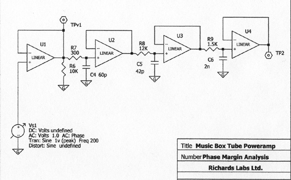
This is the model of the known poles at the high end for analysis.
Probably didn't need the first opamp. The 2nF cap in the 3rd section (capacitance of the output transformer) was calculated from knowing the approximate plate impedance of the EL34, and the rolloff frequency of the transformer from the published spec sheet. I've been told that the Hammond transformers may have a two pole roll-off charactoristic and the phase shift that comes with that. Since I'm too lazy to rig up a test jig to measure that, I'll just calculate for one pole, and see on the bench what is does.
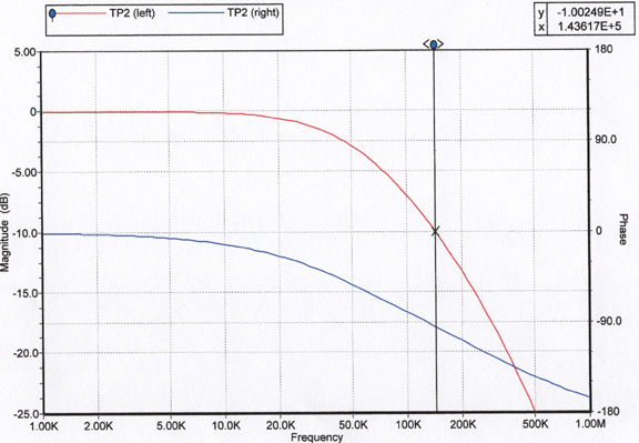
The red line is amplitude, and the blue line is phase. The vertical line is a marker at approximately the frequency where the feedback loop gain goes below one.
When I have about 10dB more open loop gain than closed loop gain, the feedback loop gain will go below one at about 144kHZ, at which point the amount of phase shift is about -100 degrees. So it's pretty far from the 180 degrees that would cause continuous oscillation, and maybe reasonably far from 270 degrees where ringing may be probable. 100 degrees is really just enough in my opinion.
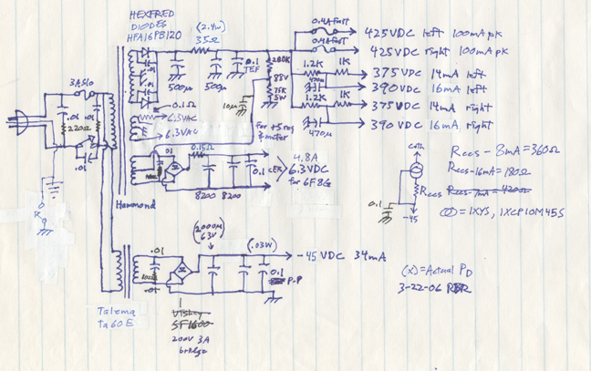
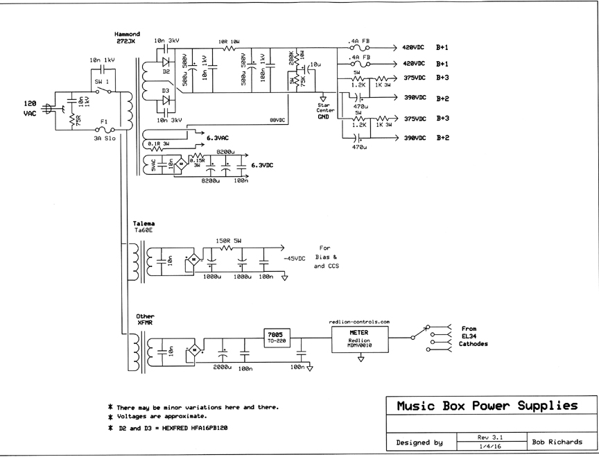
I've decided to use HFA16PB120 HEXFREDs for the B+. They seem to be the fastest and lowest noise diodes out there. DeHaviland uses them. The Hi-V outputs will have polypropylene 0.1uF caps across them, physically close to the sections being fed, with appropriate ground returns to the ground star center. The filiment supplies will be sitting up at about 90V, relative to B+ ground (circuit ground) so the cathode to heater spec (100V) in the follower stage isn't exceeded, and so no filiment hum or noise will be attracted from the filiments to the cathodes, and thereby into the signal path.
The 5V winding of the power tranny is rated at 4 amps, so once rectified can only handle the 6F8G front end tube filiments. At 0.6A per filiment (two per tube) times four you have 2.4A, and then because the 36,000 uF filter cap will provide additional loading, the convention is apparently to multiply the load current by 1.8. So you multiply 2.4 X 1.8 to get the actual current draw, which is 4.32... already a little high. All other tubes will use the regular 6.3vac winding which is rated at 8A, and by itself couldn't quite handle all tubes by itself. The 6.3 volt winding will be loaded with 8.4A, which is a little high as well. I was too lazy to draw out the little powersupply for the digital mA meter that allows one to check or set bias on each output tube easily, any time. I also later put some resistance between the two big caps in the bias supply, to reduce hum. The above schematic needs to be updated. Don't hold your breath. These are minor things that any decent tech should be able to figure out.
The third prong of the AC plug goes to the chassis plate. The switch was experimental.
The primary fuse actually needed to be changed to a 4A slo-blo. A 3 amp couldn't quite handle it.
If anyone sees any errors in any of this, please let me know.
![]()