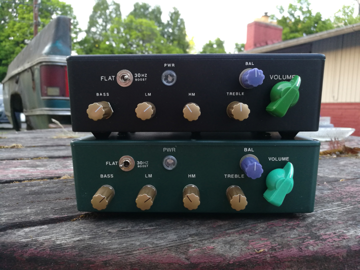
Small Tonemeister Preamp
by Bob Richards EET 2020
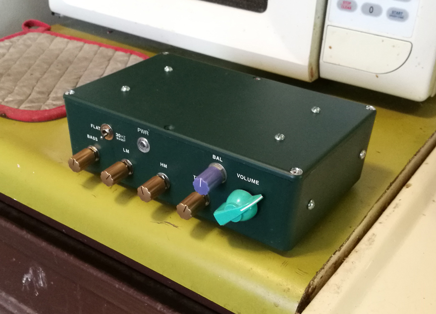
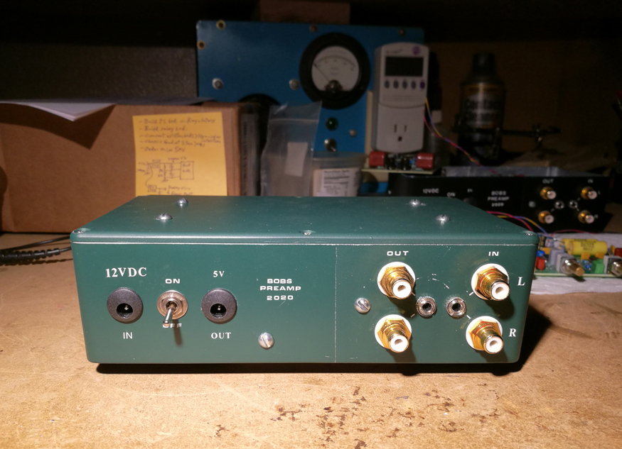
This version of this preamp is pretty much the same as my Previous
Tonemeister Preamp, but this one is optimized for a monopolar powersupply
as low as about 12 volts, rather than the more normal +/-15VDC.
When 12 volts monopolar is used to run a bipolar opamp circuit,
the 12 volts needs to be turned into a + and - supply that is regulated, so
it won't "motorboat" oscillate when put into a whole system.
So I use a low dropout regulator chip, and etc. (see schamatic)
to create a +/- 5VDC supply for the premap board and the active woofer EQ
board.
The monopolar DC input needs at least 12VDC, but can handle
up to 20VDC.
Although its less desireable to run the opamps on this lower
voltage because of the reduced headroom, most poweramps reach full output
with only 1Vms, or 1.41 Vpk, so it should work fine.
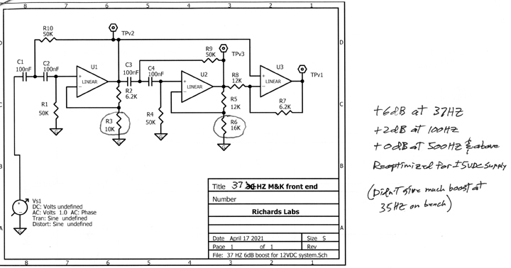
Having said that, the woofer active EQ circuit, as it turns
out, needs a higher power supply voltage (didn't know until I bench tested
it), because of how it does it's magic. Internal to the circuit, gain stages
pump up the amplitudes before combining the signals at the output mixing function.
So I had to reduce the gain in these stages, at the expense of how big of
a boost I could get at 35HZ. The results are still good, just not quite AS
good.
The graphs below show the results.
Here's my basic "Tonemeister" Preamp circuit:
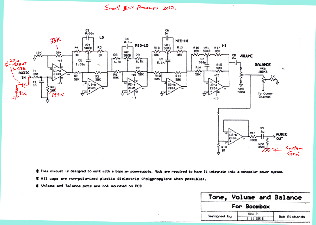
I consider good tone controls a must for several reasons:
-
Some program source material has poor EQ.
-
Most listening rooms significantly distort the frequency
response of the program source material by the time the sound waves get
to your ears.
-
The frequency response of our ears changes substantially
with sound level. Bass and high treble are harder to hear at the lower levels.
-
The bottom line goal of a music system is enjoyment, not
someones idea of neutral or flat.
Purists think tone controls add distortion and noise. Some circuits out there
do, this one is not a problem in any way in my opinion.
If you really unserstand how to use opamps, and you use high quality Rs and
Cs, I've never found them to be any problem at all.
This tone control circuit, which I desgined and lived with for decades, is
optimised for creating the perfect "Loudness Compensation" curve,
for any loudness level.
It can also help with other frequency response anomolies, but those are hard
to predict and full of variables like room size, shape. Was the record made
in the 1930's (?)
Was the Mastering Mixer guy on the ball when he adjusted the EQ? Not always.
Here's a graph of how the average human ear hears, over frequency and loudness:
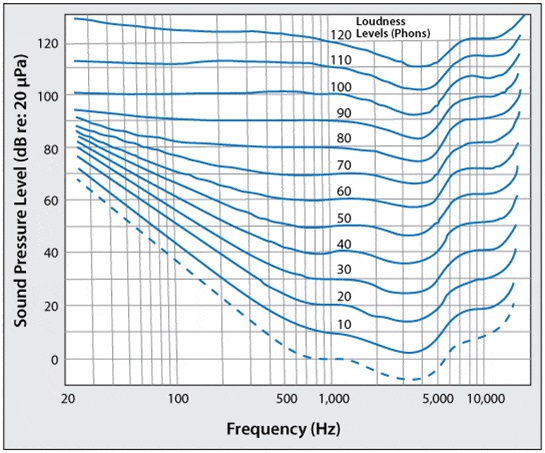
Typical listening levels in the home might be 70dB - 90dB ish. As can be seen
in the graph above, at an 80dB average loudness level, bass below 200HZ, and
treble above about 5kHZ will sound weak.
At the lower amplitude levels this gets worse.
In the old days many amps had a "Loudness Compensation" switch that
tried to compensate for this, but they never seemed to get it very right.
Room acoustics are bound to mess with the equation, as are the speakers themselves.
So I've been driven to create this tone control circuit since I was a kid.
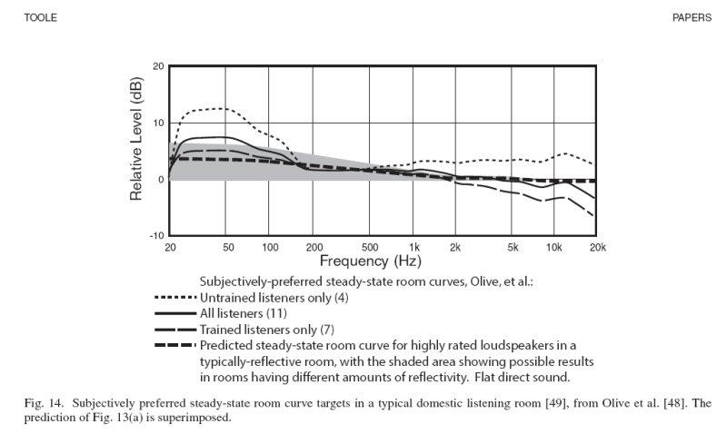
Here's another graph I found on the web of what people thought they preferred
for tone correction in one situation, with allegedly flat (neutral "accurate")
speakers:
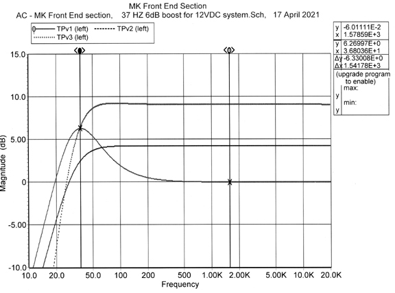
Below is the PSPICE model of the active woofer EQ board.
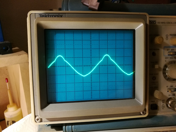
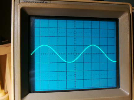
Below on the left is the internal circuit overload result. The
original circuit went bad at about 0.7 volts pk.
After reducing gains in the first two opamp circuits slightly,
I was able to get approximately 2 volts pk of headroom. Barely enough, but
there it is.
This reduced the amount of EQ boost by a few dB (from 10dB to
about 6dB), and also caused the EQ peak to move from 32HZ up to about 36HZ.
Still worth it.
Below is the power supply and output relay controller circuit.
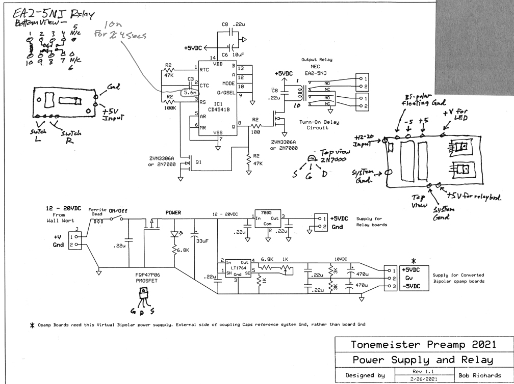
The MOSFET near the input of the power supply is there to prevent
damage in the event of applied polarity being wrong. It only conducts when
the polarity is right.
This MOSFET turned on, has a significantly lower voltage drop
across it than any diode would have. More volts is good volts with this preamp
board.
The 5 volt output on the rear of the box is for an optional
Bluetooth reciever, which would need to be outside of the grounded metal box
in order to work.
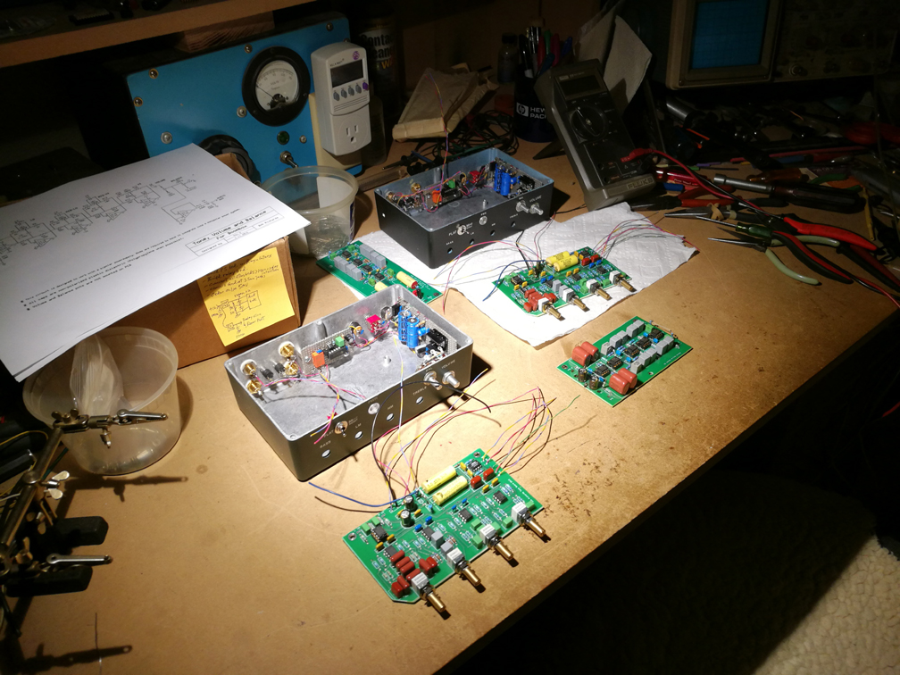
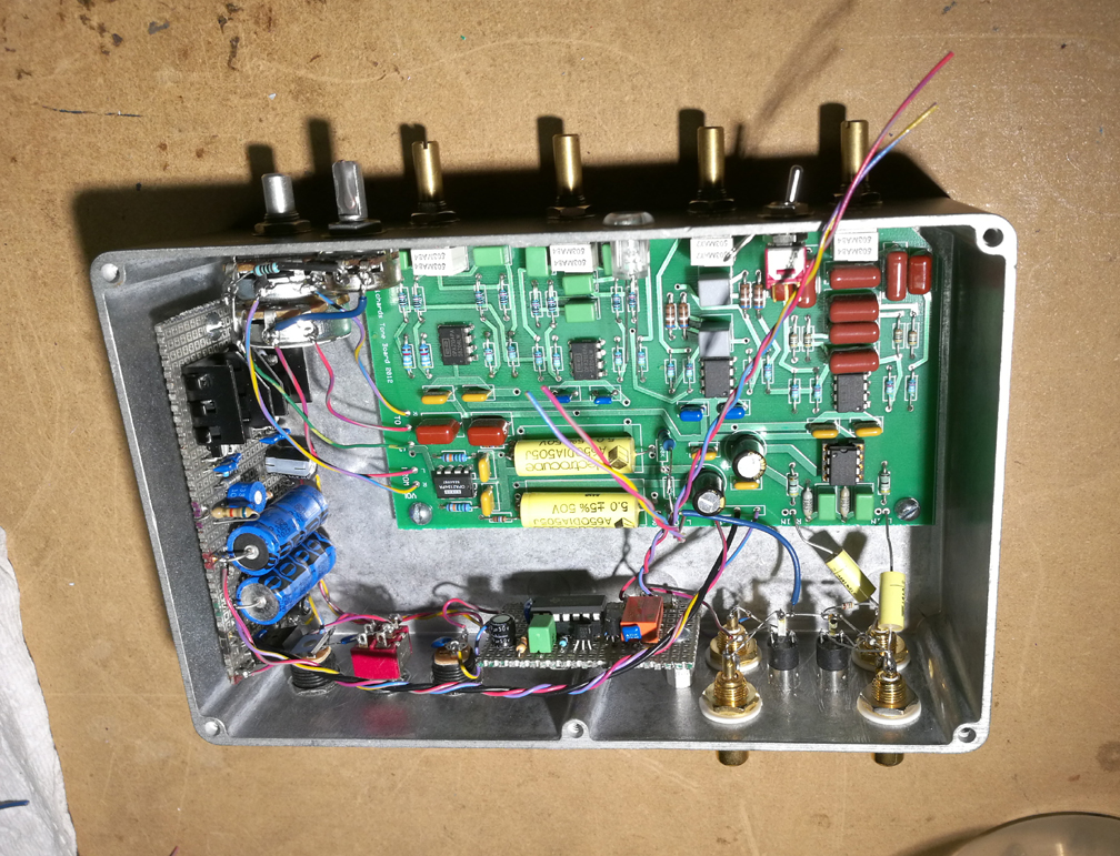
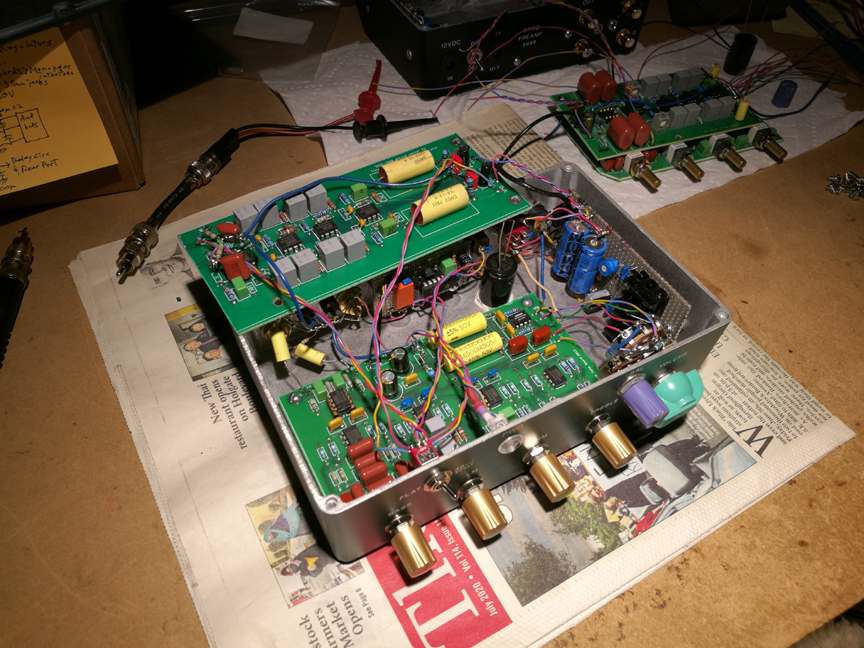
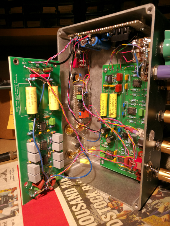
And here's a bunch of pictures of the build process. I actually
built two of these, since I already had most of the parts:
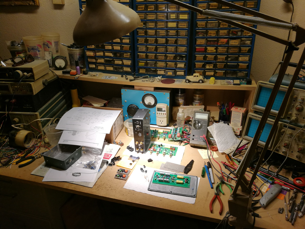
You want to attach all the wires to the boards before mounting
thm in the small cramped box. Way easier.
I guessed at the needed lengths, and then trimmed them once
in.
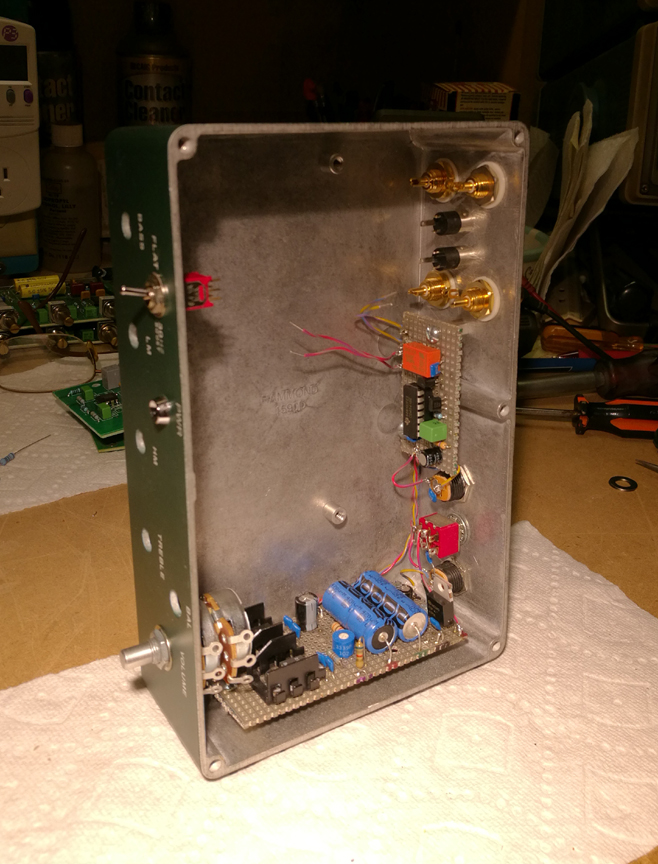
You want to install and fully test the power supply and output
relay boards, before installing the other boards, in case things aren't quite
right (they weren't).
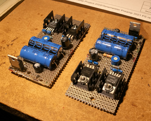
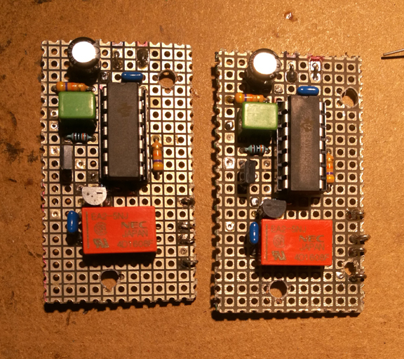
Then one more board at a time. Fully test that.
Then the last board, the active woofer EQ. That's when I found
out about the internal headroom problem mentioned above.
Finally got it right. Changing four resistors on a board that
is already wired in, is a bitch.
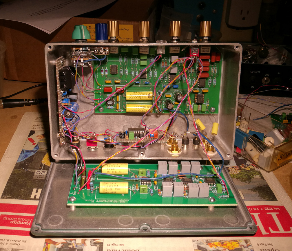
So there it is. I don't actually need these for any project
I'm currently doing, but may eventually put them in another "Boombox"
or some kind of system in a car or van.
I could use these to show Purists what they're missing, if I
cared - I don't. They will believe what they want to believe.
Some of these parts (pots and certain caps) have gotten hard
to get, so I didn't want to waste them. And I had already had the PCBs made.
The version of this preamp I used in my previous boombox project
is the same preamp board, but it didn't have the active woofer EQ board added
to it.
3 inch woofers don't do well with electronically forced low
end EQ. These tone controls give roughly +/- 12dB of boost and/or cut individually.
