Flip the switch to Mono, and you've got something generally like a Vox AC30, a 1957 Fender Twinamp or the Marshall "Bluesbreaker" amp. In the Stereo mode this amp will project the nice stereo ambience effect generated by most digital effect pedals of this era. In todays market, there are probably thousands of mono guitar amps of significant power (over 10 watts), but only a very small handful of stereo guitar amps... Many of the stereo amps that were ever made came out in the early 1960's, before anyone knew what to do with them. There was apparently a guitar or two that had two pickups with separate outputs, that would create a pseudo stereo effect. I don't know of any stereo spring reverbs or stereo echoplexes from that era outside of a recording studio. The few stereo guitar amps I could find on the web each had some kind of significant design flaw in my opinion, so I decided to research, design and build my own.
I've been designing and building Hi-Fi speakers, preamps, poweramps, signal processors, etc., since about 1970, mostly as a hobbyist at home in my lab but also while working in some high end professional engineering environments (Tektronix, Dolby Labs, a few AV companies, etc.) where the EE's encouraged me to pick their brains. I was employed as an Electronic Engineering Technician for most of 20 years before my current semi-retirement. I've been a guitarist since 1970, and have played many gigs in different types of venues in various bands. I try to play and sound like Eric Clapton; mostly bluesy, but plenty of clean digitally processed sound as well. These days I typically use compression, chorus, slap echo and reverb. The latter three pedals generate a stereo output from a mono or stereo input. Not much heavy metal. I play mostly electric but also acoustic guitars. In about 2001 a hard-core "tube-guru" friend of mine (Matt Kamna) who I met at Tektronix talked me into building something with tubes. Since then I've researched tube circuits very heavily for both hi-fi and guitar. I built one tube type Hi-Fi amp (The Musicbox project), and about 7 tube type guitar amps in the last 15 years. I was never interested in building an amp just so I could say I built it. It was always about building the amp I wanted to have, and couldn't find anywhere. So that's where I'm coming from in this vast and very subjective art.
With all the free resources on the web, any electronic tech can learn how to design a "good enough" tube type hi-fi amp or guitar amp. The kind of guitar amp I want took me into less documented areas, where it's all about the quality of the distortion and a great projected stereo effect. With Hi-Fi it's all about getting rid of all distortion. With a guitar amp it's all about tayloring the perfect distortion when you want that, and yet having a very good clean sound too when you want that. Getting a distortion that really sounds great is not as easy as I originally thought. It takes a complex mixture of various distortion mechanisms working together, and avoidance of others, to get the good stuff. The learning path has been intriguing and mostly fun.
Compared to a 30 watt mono version of this amp, you're really just adding two 12AX7 tubes, an additional output transformer, more knobs on the panel, and hopefully angling the speaker driver panels outward slightly. Maybe 20% more wiring. A 30 watt mono amp uses the same amount of output tube power as a 15/15 stereo amp. A 30 watt mono could be in the form of four EL84's (like the Vox AC-30), four 6V6's, or two 6L6's, or two EL34's. So not a huge difference really.
A 30 watt all tube stereo guitar amp with good stereo effect projection all in one box. No guitarist I ever knew would want to have to make an additional trip to the car, to get more cabinets just so he could have stereo, so I consider the all in one box feature a requirement. Very high on the priorities list is that it's got to be small and light for easy transport, but powerful enough to keep up with my idea of a typical full rock band (indoors - outdoors you mic it with the PA system if necessary). There are those who say the stereo effect gets lost in the noise of a full band. That's true to some degree. I have found that it really doesn't get lost, but it's not in your face either. It just sounds more majestic or 3-D compared to the other guitar amps in the group. When practicing at home with little other noise, the stereo effect is plenty apparent and inspiring. It makes you a better guitarist because it makes you want to play more. Yes, the guitar is mono, but the effects are in stereo. I find it to be addictive.
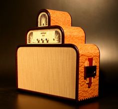
A good starting place might be looks. You've got to look at it every day, and the audience will see it. It will be a stage prop. It should look cool, without being too much of a distraction. Many people want the amp to disappear into the background. I'm a notch more expressive than that. A vintage art deco look can be very nice. Here are some examples of amps from earlier years when decorative looks were more typical (a few of them are more recent).
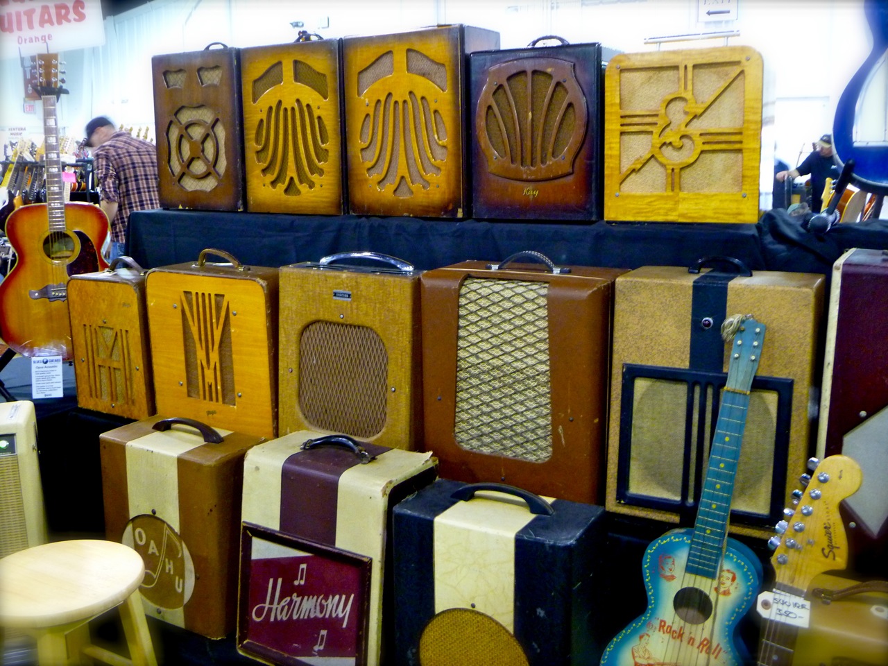

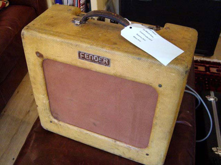
Second from the right is an early 1950's Fender "TV Front" tweed amp.
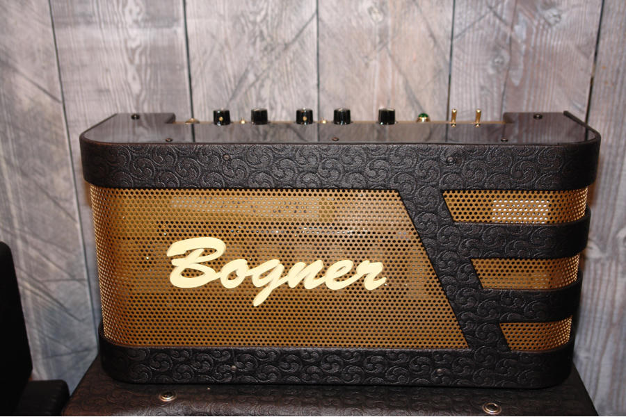
Second from the left is the Fender "woody" amp, which was the very first Fender amp. It came in 3 sizes.
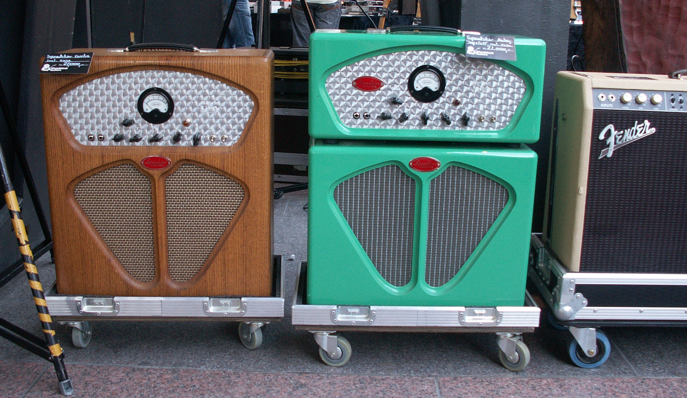
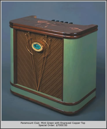
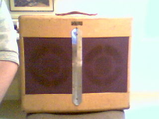
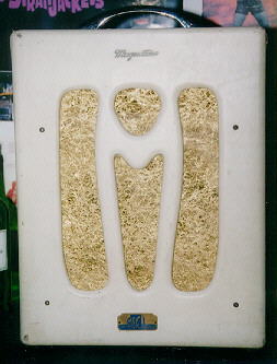
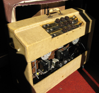
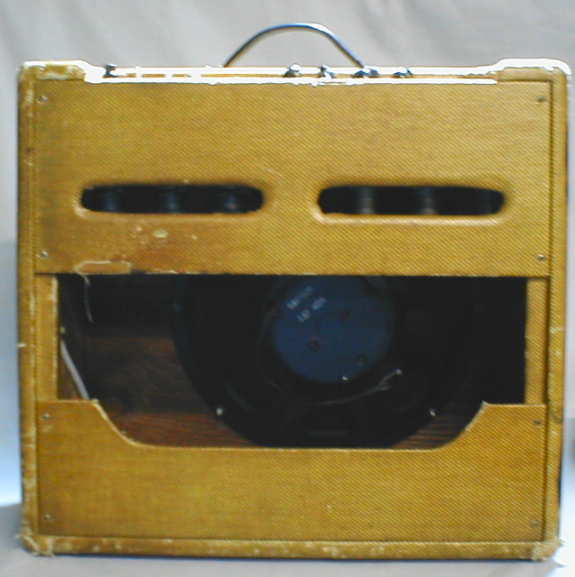
On the left is a recent "steam-punk" look. Third from the left is the 1948 Fender Dual-Pro amp with two 10 inch drivers on angled panels with the chrome decoration down the middle. Second from the right is the Gibson GA-400 with it's "waterfall" control panel. On the right is a 1950's Fender Bandmaster rear.
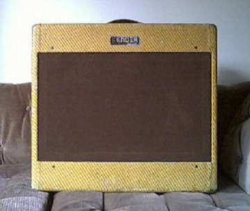
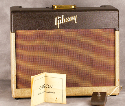
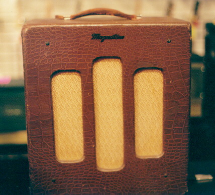
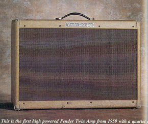
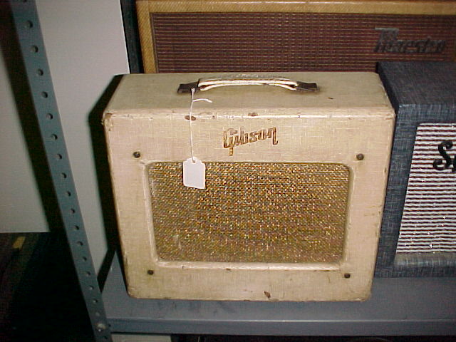
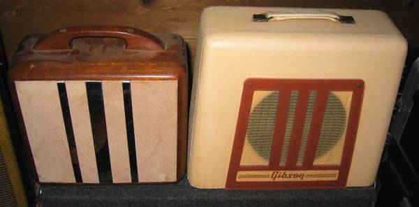
Second from the left is the 1956 Gibson GA-20t that has no blocking distortion making crossover distortion an issue. Second from the right is the 1959 Fender Twinamp. It put out 80 watts. Allegedly the first Fender amp to go beyond 40 watts.
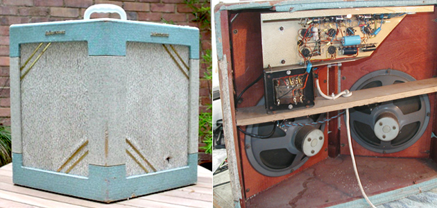
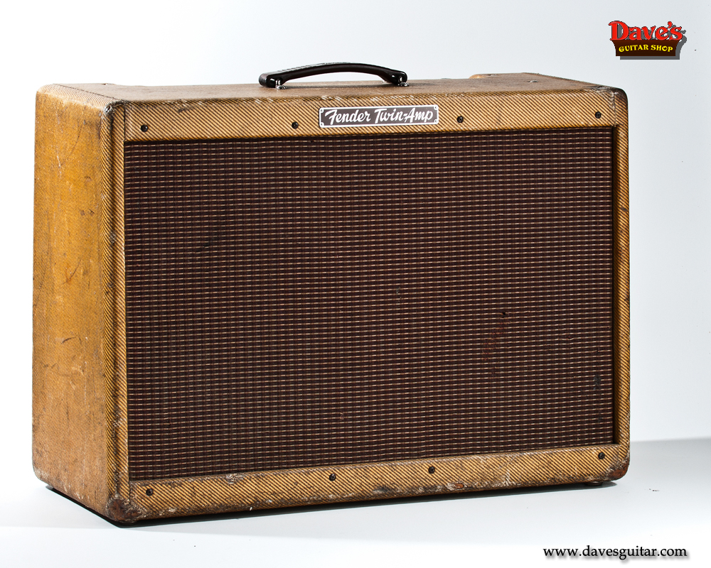
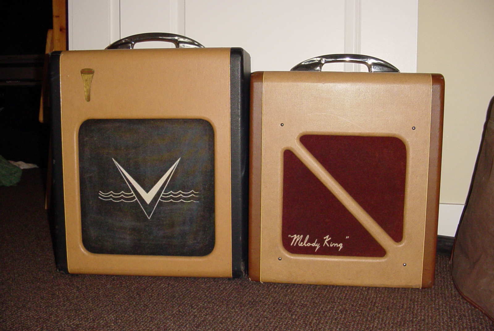
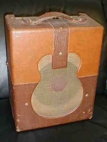
In the middle is another 50's Fender Twinamp.
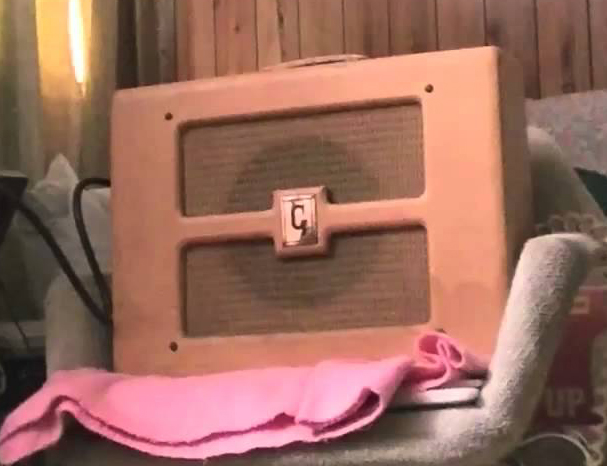
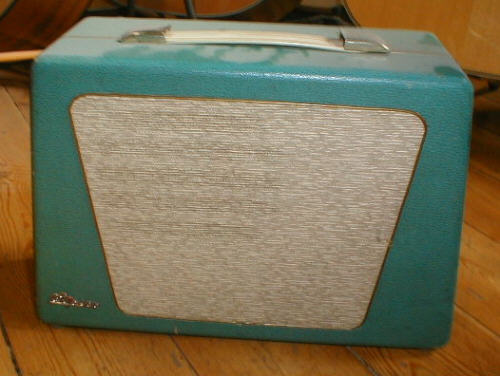
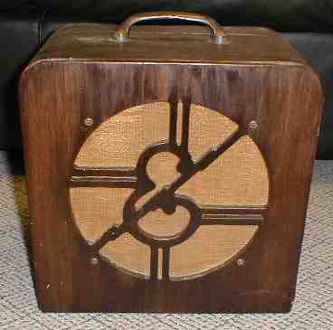
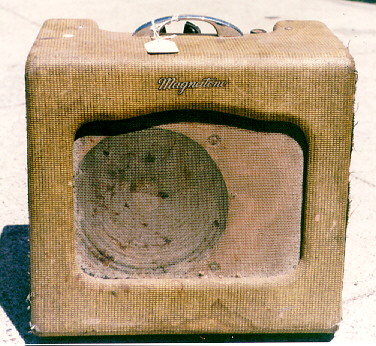
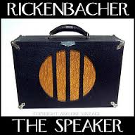
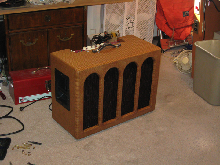
There are many more. Guitar amps were ornate art objects in the early years, and got more plain looking since about the early 1960's. I've noticed some rather ornate amps at Guitar Center more recently, which may or may not be "gimmick" amps that don't really measure up functionally. Personally I like the 1950's tweed look done in a more art deco way. Hence the arches and rounded corners. Fun to look at but not a huge attention grabber. When the cabinet puts an obstuction in front of the speaker cone; done right it can reduce the upper midrange beaminess of the sound and be more pleasant to listen to when you're on axis. Any more than the 3/4 inch bars in my design would reduce the good stereo projection at a distance. Since my amp is almost always on the floor, I prefer to have the control panel on the top of the amp, rather than the front.
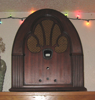
Another option if the amp is just for home use, or a low level bluegrass band, is to rebuild the insides of an antique radio. Since it's not cost effective to fix most antique radios, they're usually not real expensive. They do often have very thin walls though (especially the cathedral styles), so I've built small speaker cabinets out of 1/2 inch MDF that just fit inside the ornate radio cabinet. Otherwise I would expect vibration issues. I'd build the actual amp circuit from scratch myself. Going solid state would be much easier since it would be compact and no real heat issue. With a class D poweramp, you could run it on batteries. If you want to use tubes, I'd go with a 12AX7 and a single ended 6V6 or EL84 tenatively. Then the speaker cabinet should be open back so the tubes can stay cool.
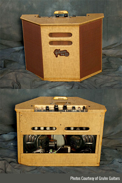
This classic Gibson stereo amp from the early 1960's was designed to work with a guitar that had a stereo output, or guitar in one channel and a mic in the other. There was a guitar that had two pickups with separate outputs which created a pseudo stereo effect. The built in spring reverb was mono. It used 6BQ5 output tubes for about 30 watts total. The power supply is in a separate chassis down at the bottom of the cabinet. The speakers are angled outward to the point that the acoustic outputs may not add very effectively at a distance (out in the audience). Probably lots of fun in a home. I read that Joe Walsh had one and liked it a lot. Probably because of the sound of the distortion (one channel is likely to clip (overdrive) at a slightly different level than the other channel, creating an overall smoother overdrive distortion).
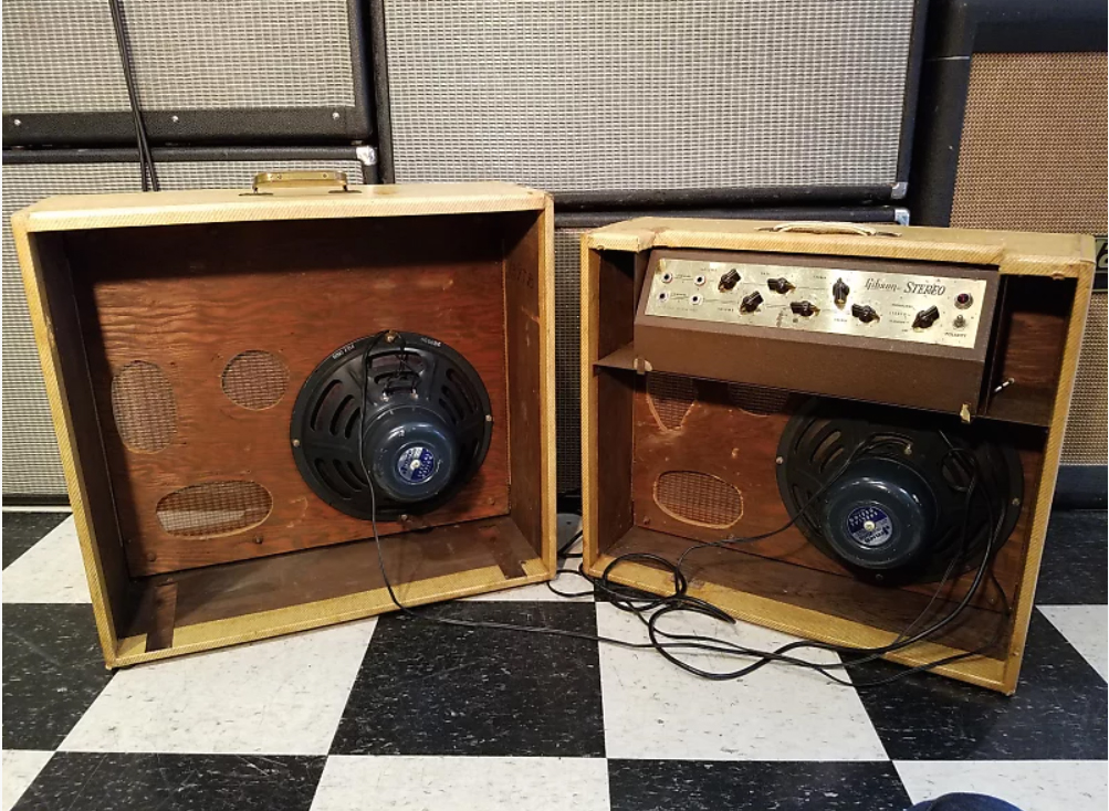
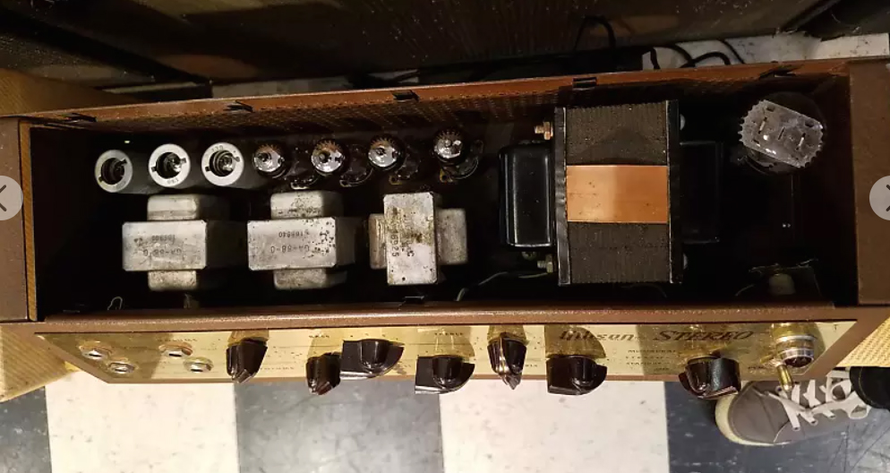
Here's another Gibson, The GA-88 from 1959. A clever design where the amp cabinet fits inside the external speaker cabinet for easy transport and storage. The EL84 power tubes may not get much ventilation, but otherwise not bad.
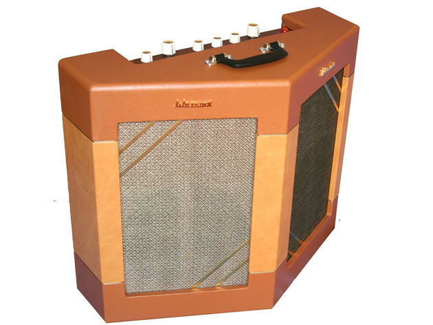
This is another vintage one. Very low wattage. It's actually a mono amp with two speakers.
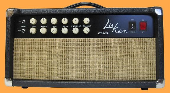
I hear this one is relatively current production, made in Eugene Oregon. Since it's just a head you'd probably be carrying in an additional load from the car to get your rig together. Might be pretty good otherwise. It uses 6V6 output tubes.
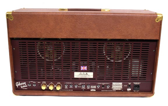
Putting the poweramp in the bottom would be a good idea for thermals, but then you can't store pedals or cords inside the back of the amp during transit.
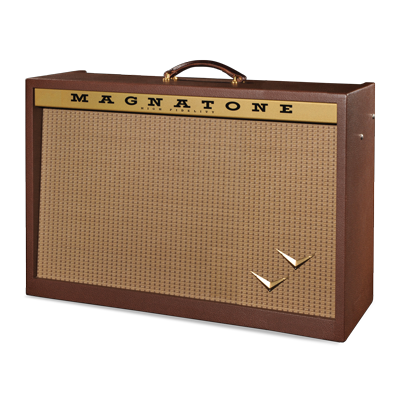
I read that Magnetone as a brand got brought back to life in recent years, and produced this all in one "stereo" guitar amp. The preamp is mono but the poweramp is stereo. The speaker drivers are not angled outward, and I hear it's very expensive and very heavy, but otherwise appears to be a great amp. It's not clear if the spring reverb generates a stereo reverb output. I'm guessing not, or they would mention it.
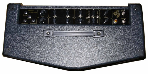
This one, custom made in Australia, possibly currently available, has 6 inch drivers aimed out the sides, in addition to the main 10 inch speakers aimed out the front. This one has slightly angled baffle panels for the large drivers (one of the very few that did that part right). Playing through it at home would probably be great, but on stage those 6 inch drivers may just be wasting power and/or projecting acoustic power to backstage, or into the side of another bandmembers amp. My experience is that the stage gets pretty crowded at most venues. You'd want to be able to switch off the side drivers when that's the case. Could look nicer. The control panel nomenclature is hard to read. Club lighting is often horrible. If I had to choose between all the stereo guitar amps that were ever made (assuming this is them), I might take this one, and replace the side firing drivers with large sunk handles for easier transport. It seems the least of the evils.
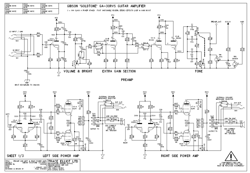
There's also The Gibson "Goldtone" series, some of which have stereo poweramp sections. They are said to be physically very heavy (about 75lbs), and not very warm sounding. They came out in the 1990's and have apparently been discontinued.
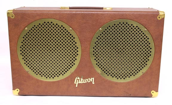

This look doesn't work for me. Speaker drivers are not angled outward. Controls at the bottom of the back???!!, The preamp is mono. Here's the schematic. It appears that you can switch in "extra gain", but not be able to adjust that gain independently... WTF...
Below is an early 1960's Guild stereo amp. It was discontinued after a few years.
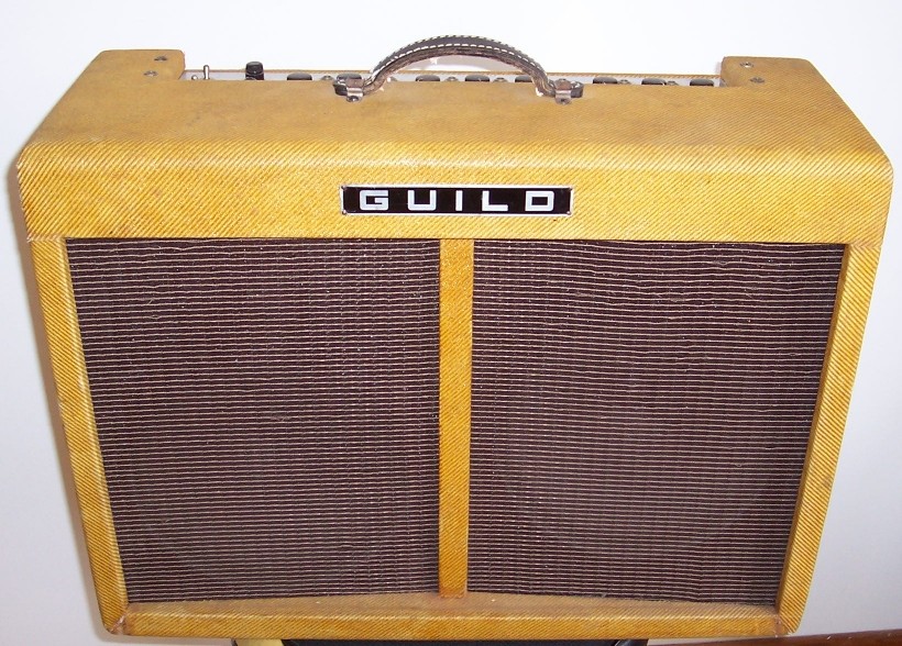
I don't know why anyone would want to angle the speaker panels this way on a stereo amp. There will be less sense of stereo effect up close, although at a distance the stereo effect should work (theoretically).
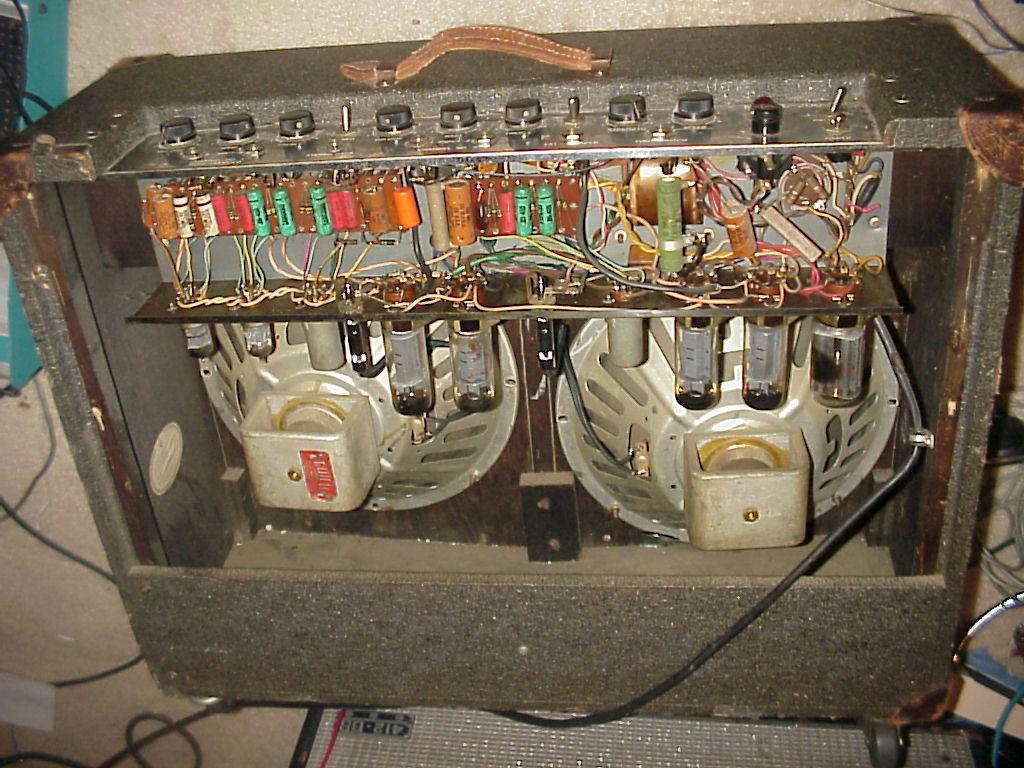
Here's the back side of it. It uses EL34's in the output stage. Running EL34's upside down, that close together, no fan, would be a significant reliability issue.
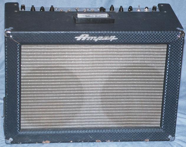
Here's the Ampeg "Super Echo Twin 2" Stereo guitar amp, the ET-1 or 2, also from the early 1960's only. Speaker panels not angled, but people in forums on the web say it had a very good "octal fatness" sound.
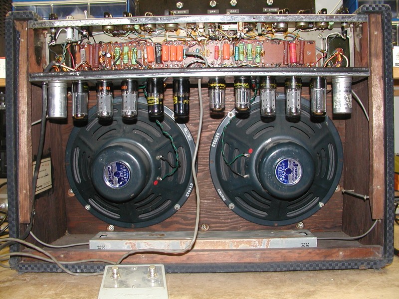
And the back side. 6V6 output tubes driven by 6SL7's. Too bad the reverb probably isn't stereo (or the ad would have said so)..
If they had used solid state rectifiers in the power supply, they could have given the 6V6's more room for dissipating heat, and kept the heat further from the electrolytics.
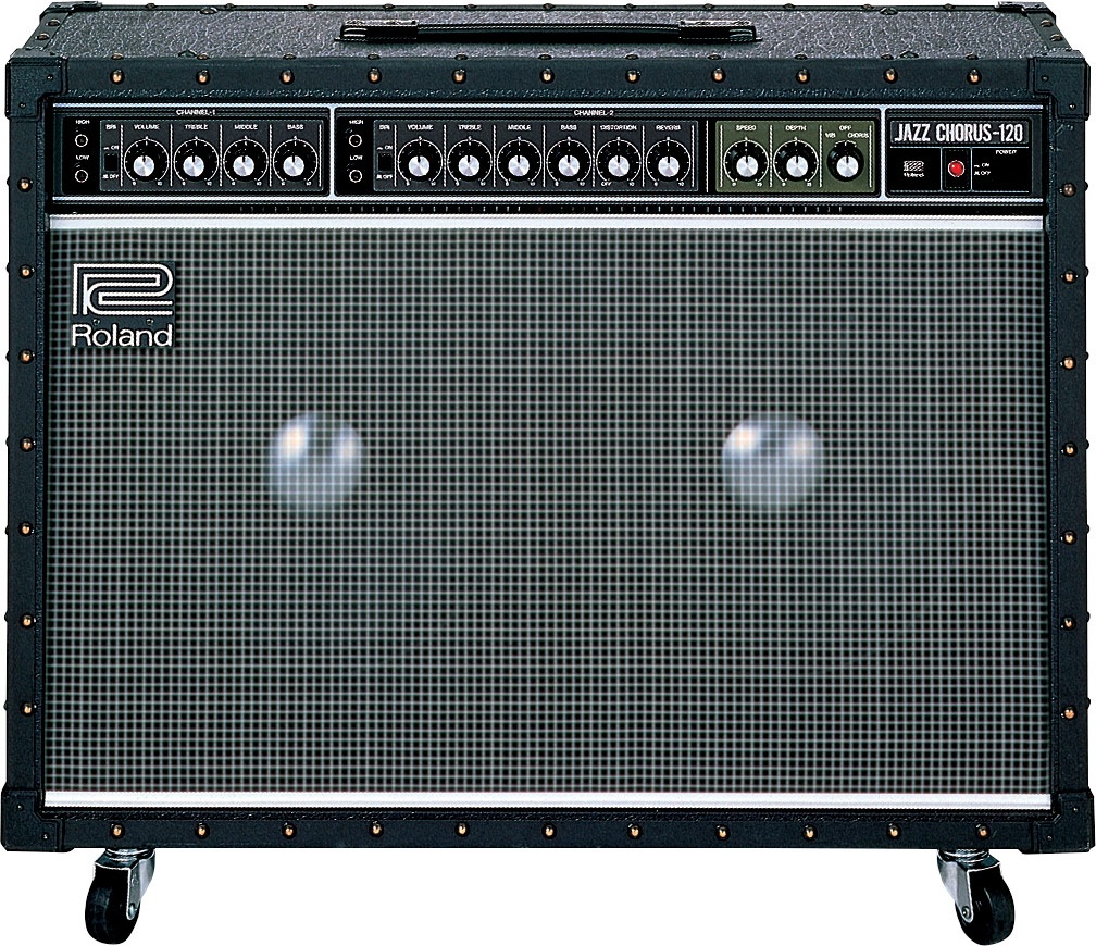
One fairly popular all transistor one is the Roland Stereo Chorus, 120 watts (They apparently make a 40 watt version too), which I think has a 2 channel preamp (hard to tell - one channel is called "normal" and the other is called "effects" according to their literature), and a stereo poweramp with external effects loop (which is usable if your external effect devices are designed for "Line Levels" rather than "Guitar Levels" - most guitar effect pedals are designed for Guitar levels, which are much lower ammplitude than Line level). It's a favorite for many jazz players who only want clean sound. But the speakers aren't angled outward, so at a distance the stereo effect may not be very apparent. The built in stereo chorus effect is said to be great sounding. I believe it's been produced for several decades, but maybe not currently. John Mayall played a Gibson ES125t guitar through one of these at a recent concert I attended (2015). It sounded real good clean.
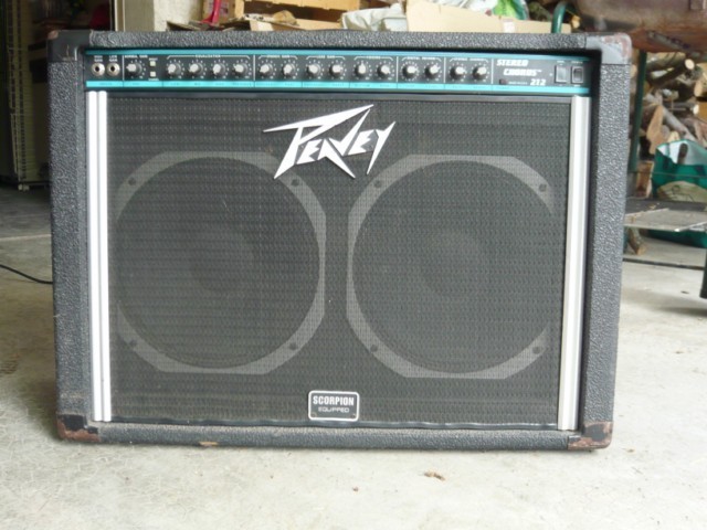
From Peavey, 130 watts solid-state
Comment from a web forum discussion:
"This is a clean amp. If you're a guy who likes to crank the amp to get breakup, you'll never in a million years be able to use it. Downsides- Heavy as hell. Brutally heavy."
Speaker drivers are not angles outward for more usable stereo effect.
In the rock and roll world, guitar related equipment gets stolen. Depending on the situation you may want to be able to carry into the venue the amp, guitar, effect pedals and cords all in one trip, so you don't EVER have to leave any equipment unattended while you make another trip to the car. Your car may not be right near the door of the club (as if that would be good enough). Hence the small light weight goal, and some storage capacity inside the back of the amp. Also in the real world, 30 watts is really just enough power for a band that does "rock music" indoors. Again it's about keeping the amp small and light. If you think you need more than 30 watts, you can mic the amp with the PA system (as Eric Clapton does with his 35 watt 1957 Fender Twinamp).
It's also arguable that you might want an amp that achieves it's best sounding overdrive distortion at reasonable sound levels. Many people feel that the best distortion sound is when the amp is pushed to near or slightly into clipping of the output stage and speakers. If it's a 100watt amp, that good sounding soft clipping of the output stage and speaker distortion won't happen until the amp is way too dam loud for most situations. Large venues outdoors are another thing. There you may actually want 60watts or more, depending on the size of the venue. I figure the PA system will probably mic my amp in any outdoor situation (they always have), so I feel that 20 - 40 watts is still the better place to be. When you have to stand right in front of your amp, it can feel way the hell too loud even at 30 watts IMO.
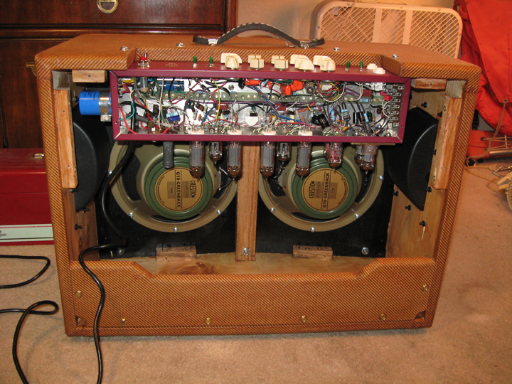
You angle the speaker driver panels outward slightly (about 5 degrees per in this case - so 10 degree differential), and depend on the fact that acoustic energy becomes significantly more directional at the higher frequencies (which it does). In a regular stereo Hi-Fi playback system, inter-aural crosstalk makes it very hard for the ear-brain mechanism to determine stereo image location below about 1kHZ, where we sense image location primarily by timing differential rather than amplitude differential, so most of the stereo effect we perceive in a regular stereo system are actually generated by the frequencies above about 1kHZ. If stereo effects work that well with that limitation in a Hi-Fi system, it should work pretty well with this design too, at a distance, where the audience is.
Ideally, you might want the 30 degrees off axis frequency response of these 10 inch drivers to be down maybe 3dB from 1kHZ on up. This depends on how far out from the cabinet you want to optimize for. If the audience is 20 ft or more out, the angle won't need to be as wide as if you are only 6 ft. out. My 5 degree number was a tradeoff with cabinet depth and cavity effect since the front of the cabinet in this case is as it is.
Below is a graph of a 12 inch speaker driver.
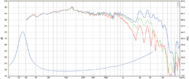
The blue curve is on-axis, the green curve is 30 degrees off axis, and the red curve is 60 degrees off axis. As you can see, this 12 inch Hi-Fi woofer starts to get significantly directional above about 1kHZ, and has a 3dB+ differential above about 2kHZ. This may seem to imply that a 30 degree differential angle would be good, but again it depends on how far away the listener will be. How far out in the audience do you want to optimize for? If I had it to do over again, I might angle my drivers slightly more (like the Austrailian amp mentioned above), but if I go too far with this in a square, flat front cabinet (which to me looks better), then I end up with significant cavity effect where the recessed panels meet the cabinet sides. I think I could go up to about 2 inches recessed on the sides before I'd guess that the cavity effects would become an issue. An angled front cabinet isn't the look I wanted. That old Gibson stereo amp from the early 1960's went with 45 degree angles. That would be nice up close, but would be weak at a distance. My amp and the Austrailian amp above went with about a 10 degree differential (5 degrees per panel). For audience members that are 10-20 feet back, the 10 degree differential should provide reasonable stereo effect. If the angle differential is too wide, the audience members at the back of the room (maybe 20ft.+ out) might not get as much high frequency energy. They might perceive a rolled off response. Your sound could get lost in the noise, sound muffled or "honky". So there's a tradeoff to be made. I'd rather error on the side of less stereo effect, then a significant high frequency rolloff at 20+ feet, so a 10 degree differential isn't a bad choice (see dwg. and photo near bottom of this page). You'll still get a noticable stereo effect up close, but the back of the room or bar will still get a pretty balanced frequency response. Since the highest note on a guitar is around 1kHZ, and since the guitar itself is mono, what you're really talking about here is the harmonics of those frequencies being effectively turned into stereo by the stereo digital reverb device (or delayer, or choruser, etc.).
I want the control panel to be simple and intuitive, so I don't lose my creative thread if I need to make a quick adjustment in the middle of a song. Most amp manufacturers try to jam as many features into an amp as they can dream up, some of which may be redundant with the controls on the guitar or pedalboard. I want just the features I really need and nothing else. As far as built in reverbs, tremolo, etc., I leave all that up to the pedal board. These days everybody has their own ideas of what effects they want to have, and as new pedals come out that often changes. If you don't want to deal with a pedal board (another trip to the car), a small reverb pedal such as the TC Audio Hall of Fame stereo reverb, or a Neunaber Wet stereo reverb or a Strymon stereo reverb pedal can be stored inside this cabinet during transit. Also perhaps a tuner pedal, choruser, delayer, a compressor, cords, wallwarts or whatever. I could have included an external loop option, so distortion of the front end could be done ahead of reverbs, which some say is better, but I found that distortion after reverb is not a problem. If the distortion is really good, you don't necessarily want that sound to get buried in the effects anyway. Plus then you need 2-3 more cables. You can always put a tube type distortion unit on the pedal board if you're that picky. I found that the TC Electronics "Mojo Mojo" distortion pedal gives me a great sound, especially when combined with the amp being slightly overdriven.
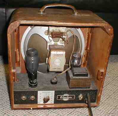
Here's a very old amp that appears to use a 300B output tube, which my tech friend Matt Kamna says has a flimsy long plate structure that would be more likely to fail due to vibration. It's a very microphonic tube. Maybe not a good choice for a guitar amp. Some Audiophiles think it sounds better in a Hi-Fi amp, where vibration is not an issue.
The 1973 edition of the RCA tube manual says power tubes should be at least 1.5 times the diameter of the tube away from other power tubes, for good tube life and reliability.
There are many examples where the Engineers ignored this wise rule.


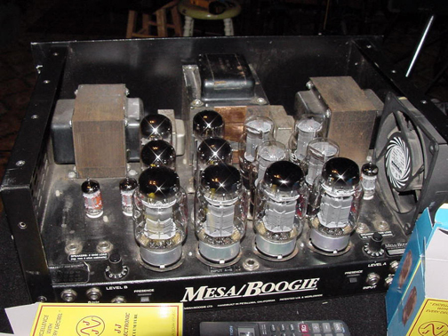
On the left, two EL34's about 3/4 inch apart, and upside down... not good. If the bases become ever so slightly conductive over time from the heat, the screen grid pin is right next to the high voltage plate pin. Any leakage there would be catastrophic. This has happened.
In the middle is an early Bob Carver Hi-Fi tube amp. A reputable person told me he had major problems with tubes going bad from too much heat. On the right is a Mesa rack mount stereo tube power amp. The Mesa does have a fan. I hope that's good enough.
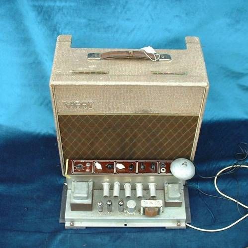
I really like some of the Vox amps for sound, but those small beer vents on top of the cabinet are how the heat gets out of the cabinet. I'm not sure if any fresh air gets in through the bottom (?). Not good.
Aspen Pitman's Tube Amp Book offers his perspective on many amps, has a variety of photos of many of the classics, and there's lots of schematics of Ampeg, Fender, Gibson, Vox, Marshall, and many other amps. These days there's that and much more on the web.
So that's the background related to this project. Now's the time to figure out how big and heavy you want the amp to be. Should it have built in reverb or do you prefer pedals anyway, and want to keep the control panel simple? Do you want more than 30 watts, or will you just mic it with the PA system when that's not enough? Do you want an amp that doesn't damage your back when you bend over putting it in the back of your car? Do you need it to fit on a rather small stage? Do you want it to achieve that good overdrive distortion at reasonable sound levels? Building your own amp is not really cost effective anymore. It only makes sense if you really want the amp to be exactly how you want it to be. I'd recommend making a list of features you want your amp to have (like I did above), so over time as you think of different ways you'd want to use it, you'll get real clear on exactly what you want. Otherwise you might as well just go buy a used amp that you consider good enough.
Since this amp is largely about having the option of generating a really good sounding distortion, it's important to be educated on the various distortion mechanisms, so you can design for the kind of "distortion casserole" you want to have.
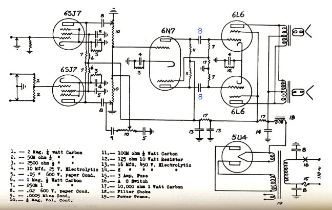
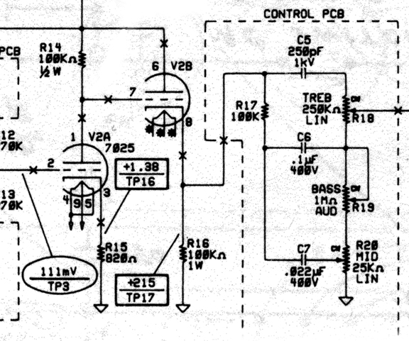
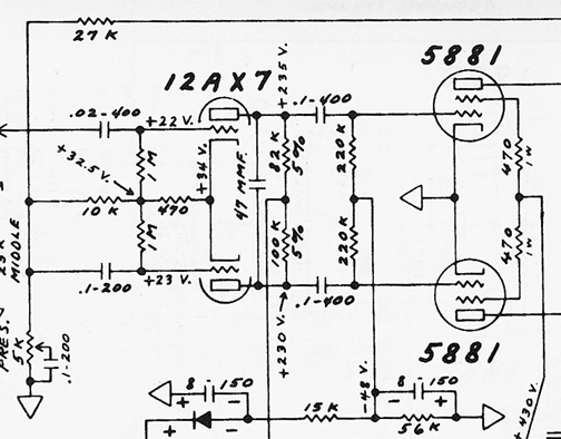
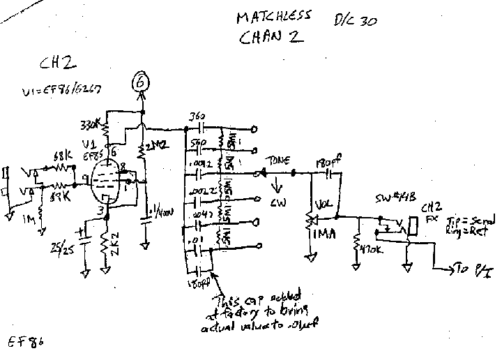
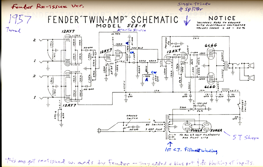
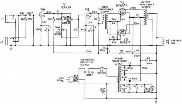
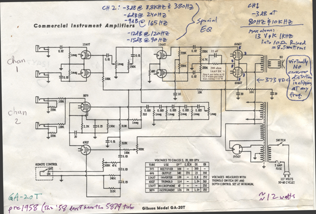
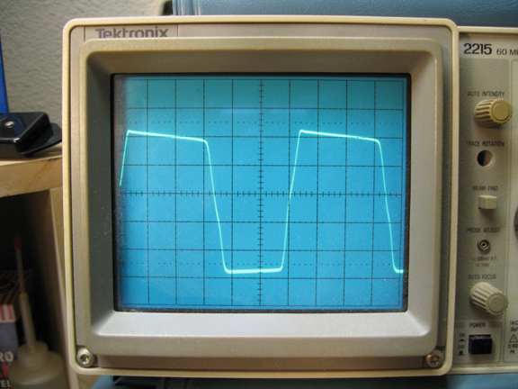
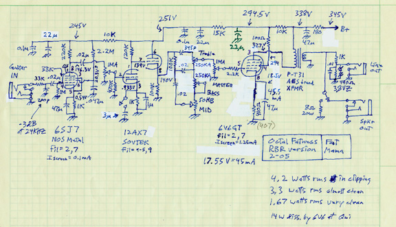
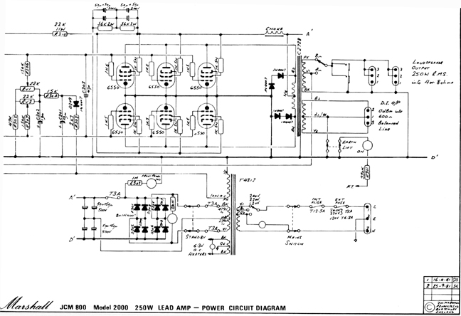
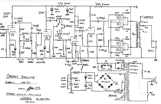
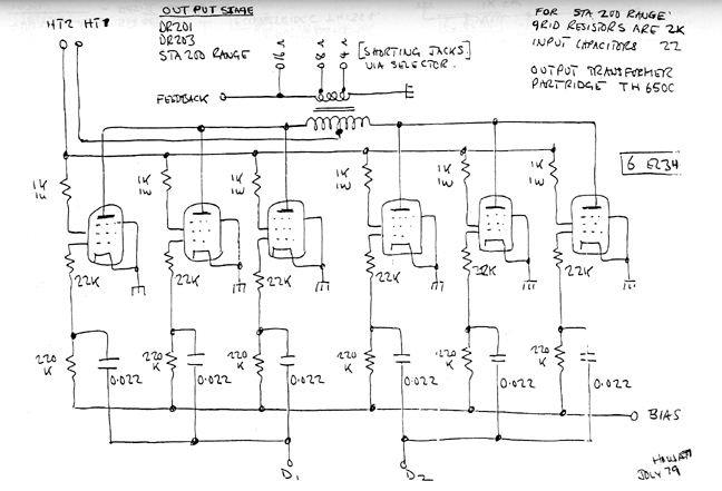
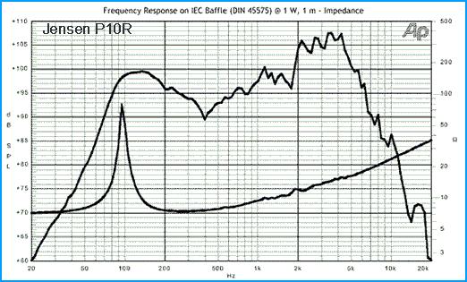
I've looked closely at dozens of "classic" guitar amps that have stood the test of time, and many more obscure ones, to see what different brands have done. Matchless has a nice pentode front end with a high pass shelf switch in some of their amps. There's of coarse the 1959 Bassman that so many guitarists consider one of the best. One mustn't forget the 1957 Fender Twinamp that Eric Clapton has been using for the last 15 years (now available as a re-issue). Some early Marshalls are notable (especially the Bluesbreaker amp). Vox surprised me with some of the best overdrive sound out there. In the Vox AC30 they have two EL84's per side of the push-pull circuit for softer clipping, and no feedback anywhere for a more relaxed sound and better overdrive distortion. A 1957 Gibson GA20t (another no feedback design) had a great overdrive sound and not the slightest bit of Blocking distortion when jammed well into clipping. Some Ampegs from the early 1960's are said to have a great bluesy sound, but tend to have higher impedance circuits (the tone stack) than they needed so may have more hum and/or hiss. Mesa and Dumble took the time to improve distortion and sustain in their own ways (Carlos Santana uses those). Soldano did a good heavy metal overdrive - more extreme than I would ever want. Many guitarists say the simple basic Fender Deluxe Reverb is their favorite amp. It goes on and on. After reading many forums on the web, I've found that opinions from guitarists should be taken with a big grain of salt. Most of them are quick to give opinions but are rather poorly educated. There are usually a lot of variables at play. While aiming for simple, I sort of took the best parts of various amps and integrated them together in my own way, and added some of my own ideas.
Coming from the Hi-Fi world, it's hard to comprehend that the electrical frequency response that sounds best with a Gibson ES335 or a Fender Stratocaster is as follows:
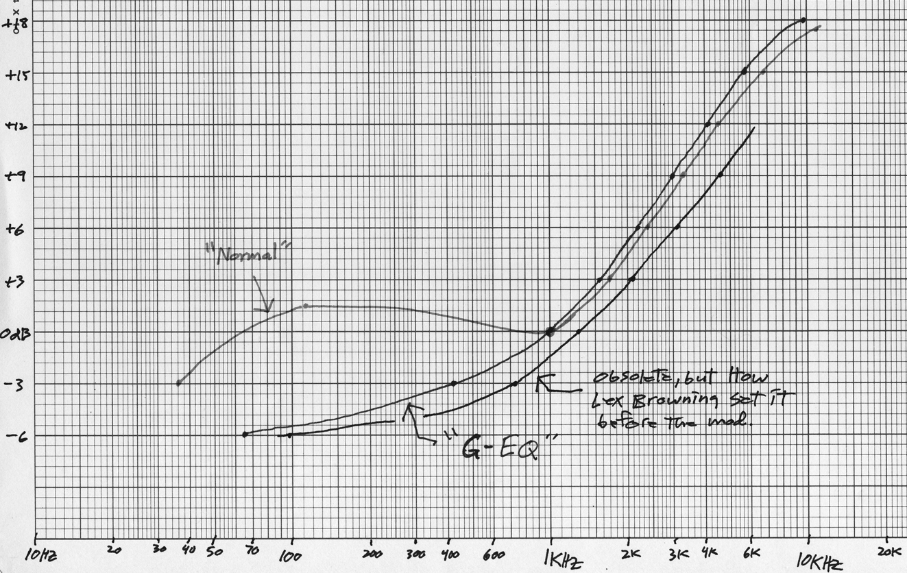
This FR was arrived at by letting Lex Browning of the Freak Mountain Ramblers set the tone controls while he test drove this amp on stage in a crowded bar. It sounded perfect to me out in the audience.
Without touching the tone controls, I took the amp home and measured the FR input to output, with a resistive load rather than the speakers, then modified the circuit so I got this with the tone controls centered.
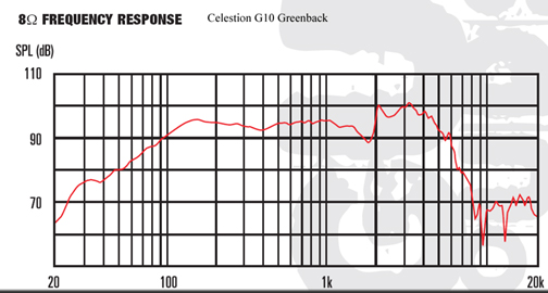
You add this graph to the graph of a typical guitar speaker graph, and it sure doesn't look like it would sound good, but it does. Electric guitars need this frequency response to sound right (but see further mod at bottom of page).
So the front panel switch labelled, G-EQ/Normal, is basically for whether the amp is on a stand or directly on the floor, where low frequencies will be more reinforced.
Many guitar amps have multiple inputs on a given channel with passive mixers at the input, which typically puts 68K resistors in the signal path. Those high value resistors add hiss noise. If you don't need multiple inputs on a given channel, you can avoid the high ohm resistors in series with the signal and have less hiss. Using metal film resistors instead of the more typical carbon composition resistors will reduce hiss too. The 1 megohm R to ground at the input gets effectively shorted out by the source impedance of the guitar, so it's noise contribution is insignificant. Paralleling two triodes cuts tube noise theoretically by 3dB+. Not a big difference but an option (Machless does it). All electric guitars that I know of are designed to drive a 1 megohm input load. If the load is lowered to 500Kohm for example, the treble will have less extension, and may be annoying to listen to. Piezo pickups are particularly sensitive to this.
To get the lowest amount of hiss and/or hum noise, you want to put most of the total amp gain in the first stage, to what ever degree that's practical. Some of the common 1st stage tubes that give good gain are the 12AX7, EF86, 6SJ7, 6SL7, etc. Many of the classic vintage amps had the 6SJ7 pentode or the 6SL7 triode. The 6SJ7 is pretty microphonic and probably less reliable than any of the other mentioned tubes. It's also not presently being produced by anyone, although there are apparently many new old stock (NOS) tubes available on the web for about $12 each. The EF86 pentode came around a little later but has been said to have more hiss noise and be less consistent from tube to tube (the NOS ones). JJ now makes their version of the EF86 (EF806s) that is very good. I've enjoyed living with it for the last five years in my 60 watt Deuce amp while playing lead guitar in a band. The 12AX7 seems to have just the right amount of gain, lower noise, better durability and is the least microphonic of the bunch, so is arguably the winner. The JJ EF806 is $30. The 12AX7 is about $12, and is made by every brand.
Having said the above, a pentode front end has that extra grid (screen grid), which if wired a certain way, might create an effect that we like, but I still need to research that more to be convinced. My toneburst generator died while trying to research that. I thought I saw envelop attack and decay distortion.
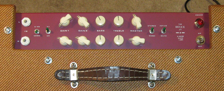
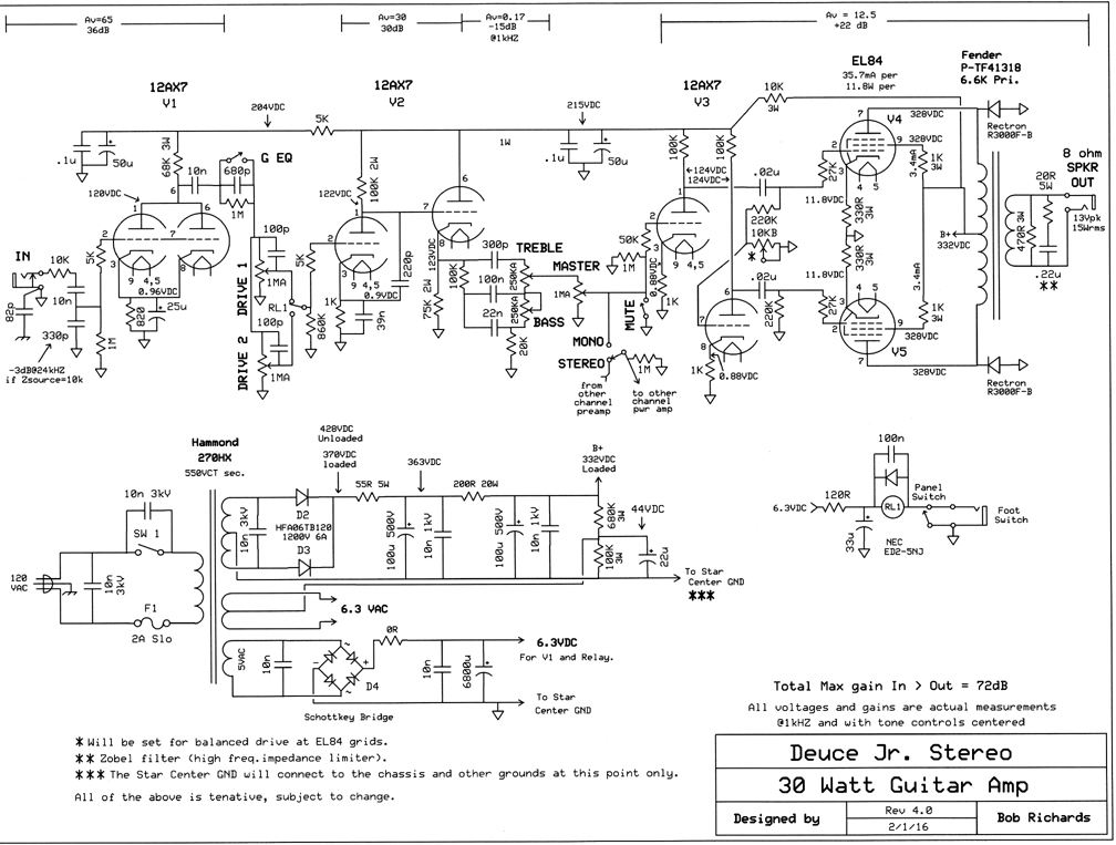
Any guitar will act as an antenna, picking up Rf energy out of the air, so a passive Rf filter at the input makes good sense, unless you like the sound of I.M. difference frequency random noise and slewing related distortions (Very few guitar amps that have this - part cost is about a dollar). Since most guitars have a source impedance in the vicinity of 12kohms or less, I added another 10K R in series with that to somewhat normalize the value (reduce variation from guitar to guitar, as viewed by the capacitor), and with a 330p cap to ground after the 10K R you get a passive Rf filter that is 3dB down at about 24kHZ. No guitar speaker that I know of has significant output above about 10kHZ, so 24kHZ is not too low. I've included a "G-EQ" switch after the first stage that compensates for room boundary effects. If the amp is placed on the floor, there may be more lower midrange and bass than you wanted. The "G-EQ" function will compensate for that. If the amp is up off the floor on some kind of stand, and not up against a wall, you might want to choose the "Normal" setting instead (see the effects in the graph above).
Once you've decided on a tube to use, based on desired gain and ability to drive the next stage, I refer to the published graphs on tube performance to determine it's best operating current, power dissipation, and bias voltage level. Since any tube can only get so conductive (never zero ohms effective), I generally prefer to fine tune the bias such that the plate at quiesence is close to 2/3 of B+ for that stage. That way you have the largest dynamic range possible, and minimal distortion. To check power dissipation, you measure the voltage across the bias resistor, divide that number by the value of the bias resistor, and then you have the current through the tube. You multiply that current by the voltage from cathode to plate (across the tube) to get the power being dissipated by the tube. It's especially important to check this with output tubes, and not likely an issue with front end tubes. Many designers have biased the front end tubes a little bit hotter (higher current, so less bias voltage), for an arguably better distortion sound if overdriven. Saturation distortion is said to sound better than cutoff distortion, and asymetric clipping will have more of the even harmonic distortion products, but also more I.M. distortion, so you don't want to over do that. There's usually plenty of dynamic range in the first stage tube to work with when the input signal is a typical electric guitar, so it's unlikely that it will ever hit clipping unless there is a booster pedal between the guitar and the amp, although other instruments (such as a pedal steel guitar) may have higher output levels that you might want to accomodate. The second stage tube is much more likely to ever hit clipping.
The common cathode triode direct coupled to the cathode follower topology is fairly common in many different guitar amps made in the 1950's and beyond, and when driven hard produces a distortion that many people like. I call it a "fullwave saturator" since when it clips, both half cycles are the result of saturation, rather than one side being a result of "cutoff" which usually has more consistent and sharper corners and sounds more like transistors. It also clips asymmetrically, which means the distortion products will necessarily include even harmonics and some audible I.M. products, and thereby sound more natural (more the way the human ear distorts). A perfectly symetrical circuit will actually lack even harmonic distortion products, and thereby produce a less natural (less pleasant) distortion sound. Ideally you want slightly more even harmonic distortion than odd. You want a fast and natural rolloff of distortion products when viewed on a spectrum analyzer, with the 2nd harmonic being larger than the third. Eric Clapton's 1957 Fender Twin Amp has the "full-wave saturator". So does the 1959 Fender Bassman amp (although neither has a Master volume control after this stage). I tried a few different tubes in this circuit topology (12AT7 and 6SL7) and felt that the 12AX7 had the best distortion sound when over driven. The cathode bypass cap was chosen to pump up the high frequency end of the Celestion Greenback a slight bit (fine tuning of the overall sound). Below about 5kHZ, the cathode resistor is effectively unbypassed, which reduces blocking distortion, which can exist in a single ended stage as well (it messes with clipping rather than creating crossover distortion).
After experimenting with the James topology (passive Baxandall), I found that the dip around 600 - 900HZ that most typical "tonestacks" have is actually desirable. A gradual rolloff below about 1kHZ (to a shelf maybe 10dB down) is also desirable. A peaking of the 6 - 10kHZ may also desirable. Many guitar speakers have this frequency response built in to some extent if you look at their frequency response graphs. A flat frequency response is good for Hi-Fi as a default, not guitar amps. I prefer to drive a tone stack from a cathode rather than a plate, so there won't be too much plate load distortion there; so the amp can sound very good clean as well. Plus then you can scale down the impedances within the tone stack for less hiss noise there. Some designs put the tone stack after the first stage rather than the 2nd stage. There are arguments on both sides. I prefer putting it after the 2nd stage so less hiss, and so the distortion-stage high-order distortion products can be rolled off if desired. The tone stack I went with is somewhat similar to the one in the 1959 Fender Bassman. It may not be the best, but it's one of my favorites. If you want major tonal variations, a graphic EQ on the pedal board might be worth looking at.
Perhaps the most common phase splitter topology is the "longtail" or "differential" topology. What bothers me about that topology is that if over time one triode of the pair loses gain, causing it's current to go down in that branch, the common current source feeding the two cathodes will cause the other triodes current to increase by close to the same amount, throwing off the balance of the circuit approximately twice as much (maybe more) as would happen with a Paraphase topology, and more than with a cathodyne topology. Many dual triodes have poor matching of gains right from the start. A Sovtec 12AX7 we looked at was way off.
Another phase splitter topology that is fairly common is the "Cathodyne", which takes outputs off both the plate and the cathode of a single triode. That phase splitter has no voltage gain by itself, so is usually driven by a common cathode stage. Although this method feeds the output stage with vastly different source impedances (so balance of drive to the output stage is likely worse, especially at high frequencies), it is the topology in the amp used by Eric Clapton (the 1957 Fender Twinamp), and in the Dynaco ST-70 HiFi amp, so it's not necessarily a horrible way to go. It's fairly common in many amps out there.
I chose to use the Paraphase topology. It was used often in the earliest guitar amps from Fender and Gibson. Arguably the more primitive topology. By adding a balance pot, you can optimize drive balance to the output stage each time you change tubes, or set it off balance by a strategic amount for a certain relatively likeable distortion in the output stage. As the tube ages, and it's gains, and therefore balance varies, the effective amount of variation will be less than half of what it would have been in the longtail differential topology. In a Hi-Fi amp I would use a 12AU7, 6SN7, or equivalent tube here, so there would be significantly less plate load distortion by the loading of the output stage. This plate load distortion amounts to real-time compression in this topology since it's driving a push-pull output stage. In a guitar amp, that compression adds sustain, and makes the overall sound smoother and less irksome. So I chose to go with another 12AX7 here.
The way I design an output stage is to pick a transformer of proper power rating, that has a primary impedance that is appropriate for the push-pull output tubes I want to use. There are ways to calculate a bunch of stuff using published graphs and a bunch of math, or you can just look at what the professional industry is doing, and what parts are readily available. Guitar amps in the 35 watt range appear to use lower impedances (heavier loading of the tubes which causes some real-time compression distortion) than if the amp is designed for hi-fi. In the hi-fi world an EL84 pair might be loaded with 8K ohms, and in the guitar world the same tubes might be loaded with something more like 4-5Kohms. I figure that anything in between is game for a guitar amp. So then I look at what output transformers are available (custom made would be much more expensive and not make a lot of difference). I found that the Fender brand transformers are much cheaper than the Hammonds, not to mention the Mercuries, so I chose the output tranny from a Fender Deluxe (about $40) which many guitarists say they love (Fender uses this xfmr with 6V6 tubes).
After wiring it all up I set the bias for about 0.7 times the power ratings of the tubes (nominally), by measuring the voltage from cathode to plate, and multiplying that by the calculated current in the cathode resistor (V/ohms = current). This isn't quite perfectly accurate since some of the cathode current (about 5%) will go out through the screen grid, rather than the plate. That's why I go with 0.7 instead of the traditional 0.65. Then I measure the voltage across the screen grid resistor, divide it by the resistor value to get the current there, which should be about 5% of the total plate currant at quiescence (no signal). To measure plate current directly, you'd need to put a ammeter in series with the plate, which really isn't necessary. If I were using fixed bias, I would put an unbypassed 1 ohm resistor off the output tube cathodes to Gnd., so I could determine the tube cathode current by measuring the voltage drop across the 1 ohm resistor (V/ohms = I ). By leaving the independent cathode resistors unbypassed, I get some real-time compression, almost no blocking distortion even well into clipping, and more sustain. I was very pleased when I discovered this. I don't know of any other guitar amp that is doing this. Putting a "Zobel" filter across the output at the speaker keeps the load impedance as seen by the transformer from ever going too high (above 20 ohms) at the highest frequencies, where all guitar speakers have a substantial impedance rise, so the output transformer primary winding won't turn into a spark coil when the amp is jammed into overdrive (clipping).
EL84 or 6V6? I chose EL84/6BQ5 output tubes with independent un-bypassed cathode bias resistors, since they have a great reputation for sound, smaller footprint, and they have no bakelite base, which can become conductive enough over time from the heat to cause problems, especially when the tubes are mounted upside down. The screen grid pin is right next to the high voltage plate pin on many of the common octal output tubes (6V6, 6L6, EL34, etc.), and the over heated bakelite base leakage is allegedly enough to throw off the screen grid bias and damage the tube, and possibly more if left unchecked for long enough. There have been many cases of "flashover" and blowout of output tubes, some parts around them, and even burnout of the output transformer and/or speaker drivers. The screen grid should NEVER glow red (either should the plate). The EL84/6BQ5 has no connections to either pin adjacent to the plate pin. Another advantage of using the EL84 over the 6V6 is the amount of bias it needs (almost a 2 to 1 difference), which subtracts from the final output power when you use cathode bias (as opposed to fixed bias), for a given power transformer and B+ voltage. On the down side, the EL84 filament draws 0.76A as opposed to the 6V6 at 0.45A, so they run hotter. The EL84 has a max power dissipation spec of 12 watts, and the 6V6 is rated at 14 watts. Many existing guitar amps out there push the output tubes beyond their max power dissipation ratings, allegedly for a better sound (?) It may be more because they want to be able to advertise a higher wattage rating for the amp so it sells better. Going from 30 watts to 40 watts only adds 1.5dB, but the typical customer will think the 40 watt amp is significantly louder. The difference is noticable, but not by much. Changing the speaker from a Greenback to a Blueback Celestion will effectively double the power of the amp (since its about 3dB more efficient), and thereby make a bigger difference in effective power if you feel that 30 watts into a Greenback is not loud enough. The EL84 also has lower max voltage ratings, compared to the 6V6 (300V vs. 350V plate volts). So if you really want 20 watts per channel instead of 15ish, the 6V6 might be the better choice. Both tubes are great sounding. Here's a comment from a forum on the web that could have some truth:
"At low volume levels the difference isn't that noticeable between [the EL84 vs 6V6] but once you get into loud clean tones and beyond (crunch and full on distortion) you really notice the difference. The EL84s have more highs so the bite and crunch is more apparent with them. Overall, they are a bit clearer [sounding] than the 6V6 and the EL84 definantly have the chime thing going on. The 6V6s don't have as much treble but are smoother overall with more bass. When you turn the amp up and use 6V6s the tone is really nice. Smooth, good compression but still plenty of clarity."
This comparison was allegedly done in an amp that was set up with a switch that would select either the 6V6 or the EL84 output tube(s), without changing anything outside of that particular circuit. These comparisons are rarely done legitimately, with all variables taken into accout. They didn't mention if it was single ended or push-pull. Both tubes are excellent. In my opinion, the best reason to use EL84s instead of 6V6 is that they take up less space in what might be a crowded chassis.
Thermals? I use ceramic tube sockets for the output tubes, since the very low thermal resistance of ceramic will help dissipate the heat into the chassis which acts as a heat sink. Ceramic tube sockets are highly unlikely to ever have the conductivity issue that bakelites can have when they get very old. Power tubes should be spaced apart by 1.5 tube diameters minimum, according to the RCA tube manual. More is obviously better. Less will shorten tube life significantly. I might add a 12 volt fan running on 7VDC (using the rectified and filtered 5V AC winding), to help the heat get out of there. Running the fan at the lower voltage gets much of the effectiveness with a lot less noise. On stage it's a non-issue, but at home at low volume, fan noise could be annoying. Adding a fan will cause the tubes to last significantly longer.
Negative Feedback and speaker damping. How the output stage interacts with the output transformer and reactive speaker load will have a substantial effect on the overall sound. Since this amp has no negative feedback, the speaker will be less tightly controlled; more free to resonate and contribute its own distortions. In Hi-Fi land this is ususally considered a bad thing. In guitar amps I find that it produces a warmer and more relaxed sound. If you want the bubbly breakup distortion in the low end, and a rich creamy sounding midrange and treble, no feedback will help that happen. Smaller speaker magnets help that as well, but at the expense of bass tightness. Those who always want clean and tight bass might want to use bigger speaker magnets and some negative feedback from the output back to the phase splitter stage, so the output Z of the amp is significantly lower, and thereby more able to tightly control the speaker reactance and resonance.
They say you should never operate a screen grid at a higher voltage than the plate. Many amps tie the screen grid to B+ with a current limiting resistor and a bypass cap at the screen grid. Some of the earliest amps didn't include the screen grid resistor which often caused the screen grid to glow red, which led to tube failure before long. As soon as the screen grid draws any current, a voltage will drop across it's resistor, so the resistor will drop voltage and limit current, and thereby power dissipation. If you have a current limiting resistor that respects the power dissipation rating of the screen grid, you're doing it right. Although it's "traditional" to adjust the screen grid current to about 5% of what plate current will be at quiesence, as long as you respect the power dissipation rating of the screen grid, there is some flexibility there. The voltage at the screen grid will affect the gain of the tube. The screen grid resistor in a push-pull circuit if not bypassed with a cap will cause some real-time dynamic range compression and thereby increase sustain. It also reduces Blocking Distortion. More on that below.
The diodes from the output tube plates to ground are a new thing for me. Although I show them in the schematic, I didn't actually bother with them, since I've got an impedance normalizer ("Zobel" filter) at the speaker. I've read that these diodes can affect the overdrive sound some. The output transformer can produce several thousand volt transients when it's jammed into clipping, if the transformer is not loaded properly at all frequencies. This can cause blowouts of the output tubes, output transformer and/or speakers. The diodes are said to absorb those transients and keep things safer. Very few guitar amps bother with these. If the speaker connection ever became intermittent during use, this would be a big issue. The 470R resistor across the secondary of the output transformer is better than nothing for limiting this potential disaster, in case the speaker does go intermittent or burns out (open). It throws away about a watt and reduces the potential voltage spike some. Putting the "Zobel" filter across the speaker terminals (20 ohm R and .22u cap) keeps the speaker impedance from rising so high (at very high frequencies) that the output transformer could generate severe voltage transients when the amp is over driven into clipping.
Last but not least, "Blocking Distortion". Any push-pull output stage will give you substantially better efficiency than a single ended class A output stage, but it can have "crossover distortion" at the zero crossing of the waveform, when one tube is turning off while the complimentary tube is turning on. Although some crossover distortion by itself is not necessarily a horrible thing in a guitar amp, there's another distortion mechanism that shows up as severe crossover distortion on the bench, called blocking distortion. It's where the over driven tube draws grid current enough to charge the upstream coupling capacitor such that the bias is effectively reduced to the point of generating substantial sharp-cornered crossover distortion. The circuit goes into class C operation temporarily. It's contribution to the overall distortion is not pleasantly musically related to the signal from the guitar. I therefore made it a goal to have NO blocking distortion when the amp is overdriven well into clipping. Almost all push-pull amps out there have this insideous distortion. Getting rid of it can be a bit challenging. There are several methods I know of for getting rid of it:
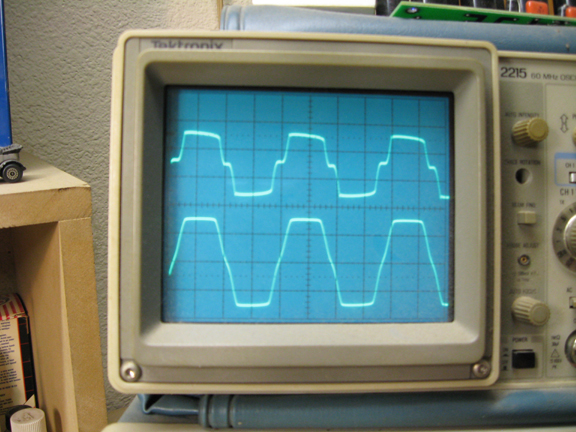
Most properly biased push-pull circuits work fine up to clipping, but become ugly when pushed into clipping, as a guitar amp will do for effect. Things can get even stranger if there's significant negative feedback, because the negative feedback becomes momentarily inactive once the amp is in clipping.
When a waveform comes out of clipping, there is a recovery time (it's not always clean and instantaneous).
The upper trace shows typical crossover distortion when blocking distortion is active (causing temporary class C operation) (the vast majority of the amps out there) .
The lower trace shows typical crossover distortion when blocking distortion is not active (consistant class AB operation). It's those sharp corners that generate the high order distortion products that can be a bit much ("transistor sound").
I agree with those who say that using a tube for rectification is foolish. It generates heat, uses significant space, and pushes the power transformer closer to saturation. If you do the grounding correctly, the amplifier circuit has no way of knowing the difference between tube and solid state rectifier diodes. I use fast recovery diodes (HEXFRED's) and anti-transient caps to minimize any switching noise (which happens at the zero volt crossing). If you want "sag", you add a certain R and C after your main power supply filtering to get that. A tyical rectifier tube will present a resistance of roughly 40 ohms, so that gives one a starting point. Many power supplies in the coveted early amps from the 1950's and 60's had very little filtering in their power supplies, largely because nobody made large value electrolytic caps in those days. Many of those early amps hum significantly at quiescence, and when the output stage clips it loses it's ability to cancel hum, so the sound is suddenly modulated by 120HZ... There may be a song where adding a 120HZ note is musically helpful, but not likely. I also don't like chokes. They take up significant space, add significant weight, and could interact electromagnetically with other parts, and just aren't needed now that large cap sizes are easily available. A choke is more efficient, but who cares. It's also more reactive when the amp is turned on or off, and can cause voltage spikes. A double RC filter works great. You just need to pick a power transformer that allows you to throw away some voltage (maybe 40 volts) in the RC filters. In this amp I throw away about 38 volts there. Since voltage is a squared term in the power formula, you don't want to let that B+ voltage get too low.
When you are running 10 tubes (as this amp does), you want to pay attention to the max current ratings of the filament windings of the power transformer. The often available 5VAC winding can be rectified and filtered, which will give you about 7VDC, which can be used with a dropping resistor to drive the filaments of the front end tube(s), if that makes better sense (I had to do this since the EL84 filaments are very thirsty). Running the first stage filaments on DC will reduce hum too.
And then there is the heater to cathode max voltage spec that most Engineers have ignored over the years. In the cathode follower topolgy (which drives the tonestack), the cathode will be held at roughly half to 2/3 of B+ voltage, while the heater is typically within 6.3 volts of ground. To make this far less of an issue, you use a tapped bleeder resistor across the final B+, which might give you a roughly 90 volt reference for the filiment supply (I went with 44VDC but probably should have gone higher). This reduces the likeyhood of there being a problem with that, and also reduces hum that can be caused by the cathode, acting as a plate, being more positive than the heater acting as a cathode.
There are those who believe carbon composition resistors sound better, and more like the original vintage amps which all had them. I don't believe that there is any difference at all in the audio frequency range except that carbon comps hiss more, which could affect ones perception of the overall sound. I prefer to use all metal film 1% resistors throughout the front end to minimize the hiss noise, and anywhere else where the value is over about 5k, except for in the power supply or output stage, where I prefer metal oxide or wirewound resistors.
I prefer to use cheap polypropylene caps (Solen or Orange drop, for ex.) everywhere in the signal path. Any polypropylenes are extremely low distortion. Buying the more expensive versions of polyprops is highly unlikely to make any audible difference. I prefer to use ceramic 0.01uF 3kV caps across any electrolytics in the power supply, across the rectifier diodes (or just the secondary of the transformer) in the power supply, across the AC input (hot to cold) and across the power switch in the primary AC circuit (the switch will last a lot longer, and not cause a loud transient out the speaker when turning off the amp). When choosing voltage ratings for the power supply electrolytics, don't forget that the B+ will be significantly higher when the amp is first turned on, after the caps charge, but before the tubes warm up and start to conduct, thereby loading down the B+ supply.
Jamming a 35 watt stereo guitar amp into a 17 x 4 x 3 stock Hammond aluminum chassis is not easy. You need to plan carefully. There's really just barely enough room for all the stuff you want to have. Some of the issues are thermal, proximity to speaker magnets, and oscillation due to unintentional positive feedback through the air if layout and wiring isn't done right. Many existing guitar amps have high power output tubes way too close to each other, which will shorten their life a bunch. The RCA Tube Manual (1973 edition) says power tubes should be spaced apart by a minimum of 1.5 times their diameter. I've read that "beam power tubes" (6V6, 6L6, etc.) are more sensitive to magnetic fields from speaker magnets and/or power transformers than EL84 and EL34, which are "true pentodes". If you keep any high impedance input stage wiring away from power supply and especially output wiring, oscillation due to positive feedback through the air is unlikely, but the finished amp should be looked at with a 1kHZ and 10kHZ squarewave on an oscilloscope to make sure ringing isn't too significant (an indication of instability). There's always some ringing, but it should be less than about 5% when the amp is driving an appropriate value load resistor.
Below is a tentative drawing of what I came up with for chassis layout (I forgot the balance pots and the foot switch jack). I still might change something, but this should be about final. The input stage tube sockets are mounted on a 1/8 inch thick brass plate that's sitting on some special soft rubber grommets. The brass plate is fairly heavy, and the grommets are made of a very flexible rubber, softer than conventional silicone rubber. This shock mounting absorbs vibration such that there is no feedback when the amp is turned up all the way with the inputs shorted. Any front end tube will be highly microphonic when there's a voltage gain of more than 1000 (which is typical of most guitar amps). Such feedback may or may not be good sounding. I did this in my 60watt Deuce Stereo amp, and it worked great. So I did it with this amp too. I don't know of any commercial guitar amps that bother doing this, but maybe that's why Bob Poletki of Eurotubes (very experienced) says he hates "combo amps", where the amp and the speaker(s) are in the same cabinet.
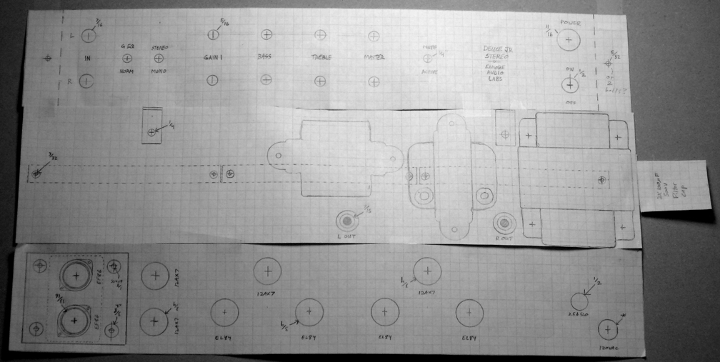
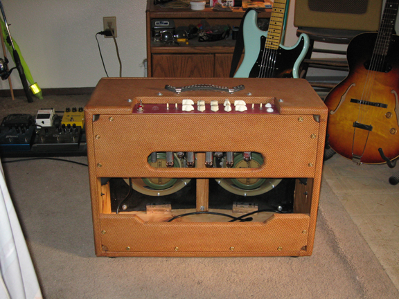
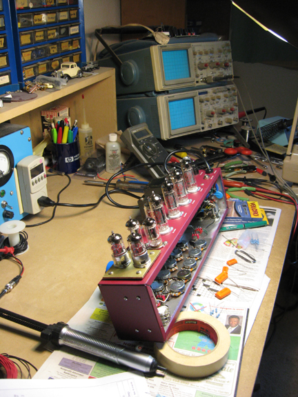
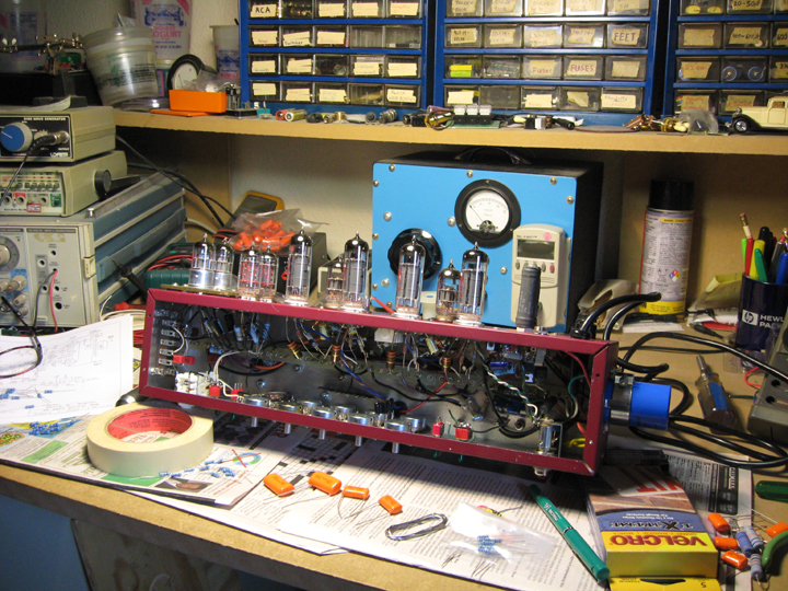
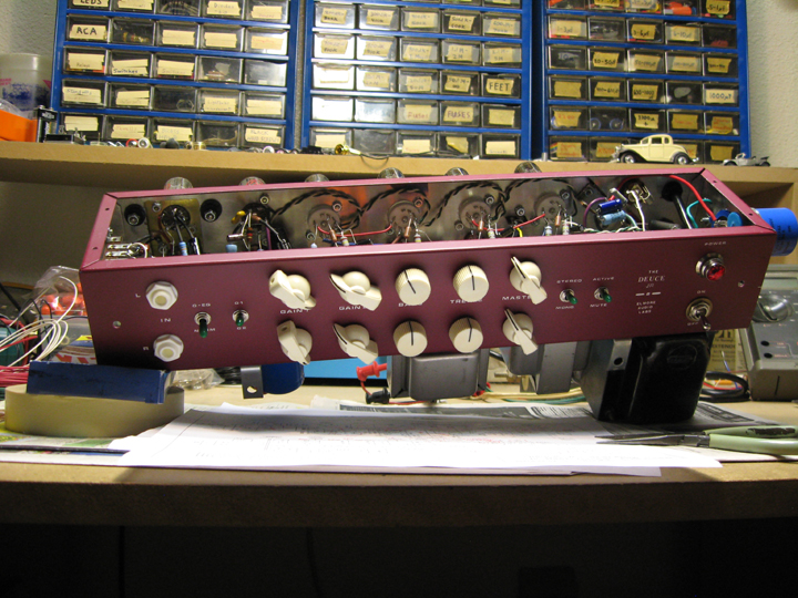
I scotch taped the drawings of the three sides of the chassis together so I could fold it and realize what could get in the way of what internally. Specifically, I hadn't noticed that the output jacks, which will protrude into the chassis about an inch, would have gotten in the way of the output tube socket wiring, if I hadn't done this (so I moved them). This helps you think of everything up front. Transformers can be close to each other if their cores are at right angles to each other, otherwise they will couple their signals. Since the transformers are pretty heavy, I decided to add 2 L-brackets to the back side of the chassis (see in photo below) to give the aluminum chassis more strength. At one point I was going to put the power supply in a separate chassis in the bottom of the cabinet, but besides the awkwardness of the wiring connecting the two chassis, the power transformer got a bit close to the speaker magnets. How bad that would be is hard to tell until the whole thing is done. Plus then it would be hard to store effect pedals and cords inside the cabinet during transport. The thing sticking out of the right hand end of the chassis is the 2 x 100uF 500V filter cap. I was thrilled when I realized I could get it further away from the heat of the output tubes by putting it there. Electrolytics don't like heat.
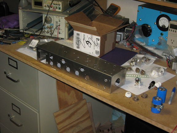
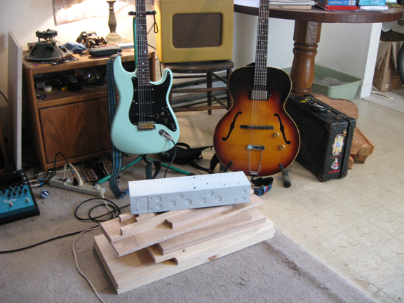
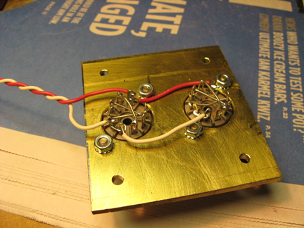
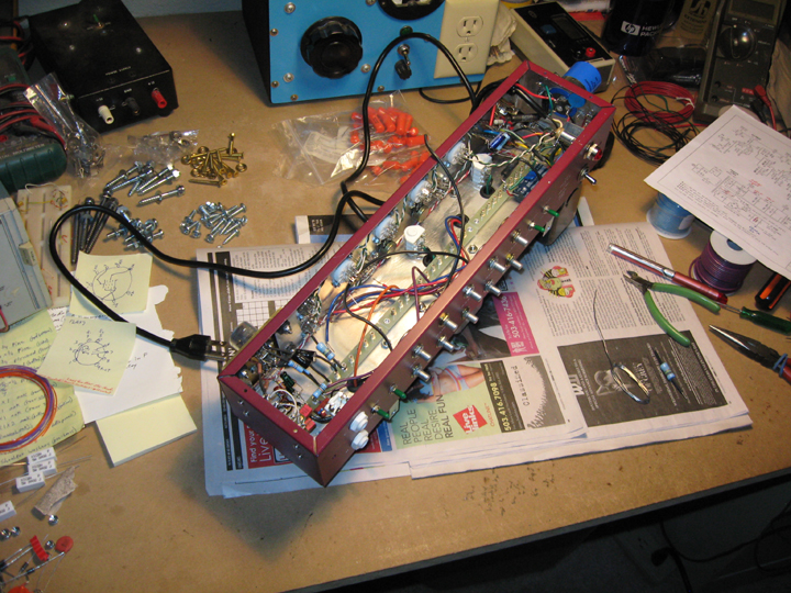
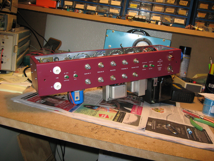
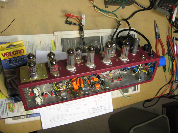
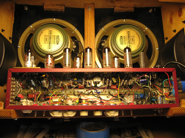
Since I wanted the speaker panels to aim outward slightly for a better stereo effect at a distance, I had to either build a cabinet with an angled front (which to me has a weird look), or hide the angled front panels inside of a second front. I chose the latter, at the expense of lighter weight, because I want the amp to have a certain relatively normal look. The decorative 2nd front is actually very light weight (it's 3/4 inch plywood - I needed light weight and durability). The rest of the cabinet is all solid pine, with oak bracing. Pine is said to sound better, and is light, but not as durable as plywood. Oak is very strong but heavy, so I used it sparingly.
The thing about angling the speakers outward is that you want the acoustic outputs to largely add at a distance at the lower frequencies (below about 500HZ), so you get both channels worth of power and warmth at a distance, but you also want some separation in the upper frequencies (above about 500HZ) so the stereo effect will be more apparent at a distance. Since acoustic energy coming out of a speaker driver becomes significantly more directional as you go up in frequency, you can get a significant stereo effect at a distance in the upper frequencies, while maintaining the effective power and warmth of both channels in the lower frequencies.
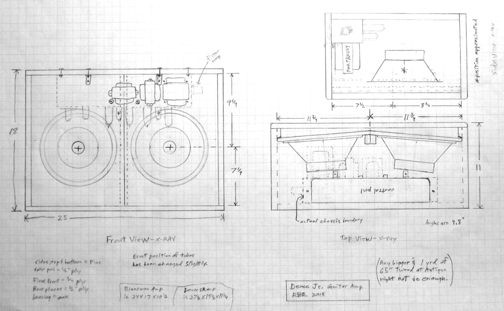
It's a bit time consuming to measure everything so you can draw things to scale. If you don't do these drawings before building an amp, you are asking for major trouble. Same as with the chassis layout. I actually sort of enjoy this part.
The plan says the cabinet is 11 inches deep, which it should have been. I made it 12 inches deep, because I had enough wood, and figured it would be better to have more space between the speaker magnets and the tubes. Now the cabinet is deeper than it needed to be.
Having said that, it's nice to have an amp that you can put stuff on; a beer, a coffee, a phone, reading glasses, an ashtray, a shot of wiskey, music papers, or just that you can sit on some of the time. It may be the only "table" near by at a jam session.
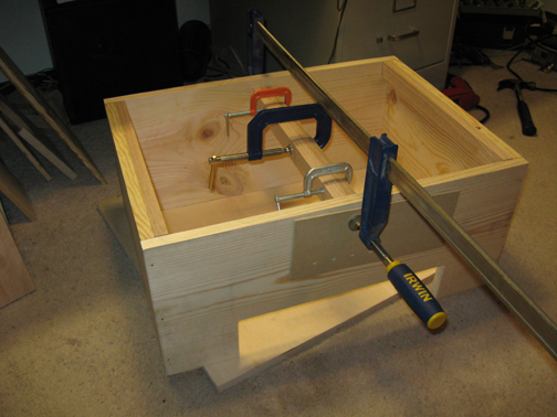
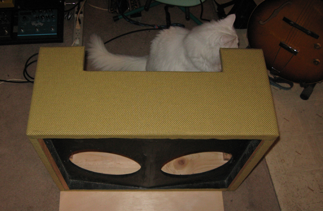
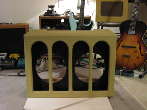
I don't bother with fancy finger joint corners, but I am very picky about clamping and allowing wood glue to dry for at least 24 hours before touching it. When buying pine wood, make sure the boards aren't too warped (most were at Home Depot).
I rounded most of the corners with a 1/2 inch radius router bit, before applying the tweed covering, for a mellower look (I hate sharp corners!). Fender used pine in the 1950's, but they use plywood these days. Plywood is more durable but can have problems with a router. Clapton allegedly prefers the sound of pine.
Gluing the tweed covering on and then staining it is probably my least favorite part of the process. Bad fumes, you need to wear gloves the whole time, and it can be messy. Same as with painting the chassis. You don't want to do any of that indoors, and it must be over 60 degrees F outside.
I use an amber shellac or oil based stain with a little red food coloring added to adjust the colortone of the tweed (personal taste). It also makes the tweed more durable. I did all the panel lettering with dry transfer letters, one letter at a time (difficult and time consuming), because it looks great, and a one-off panel silk screened is a bit expensive. So you spray the aluminum chassis with aluminum primer, then a color, then letter it, then spray 2 coats of matt clear over that. The primer needs to actually say "aluminum primer" on the can, or it isn't good enough. I learned this the hard way.


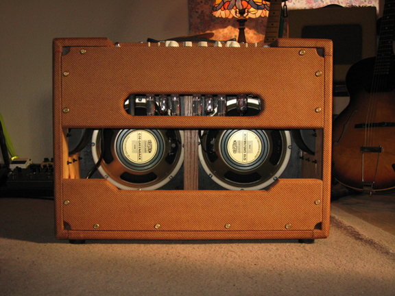
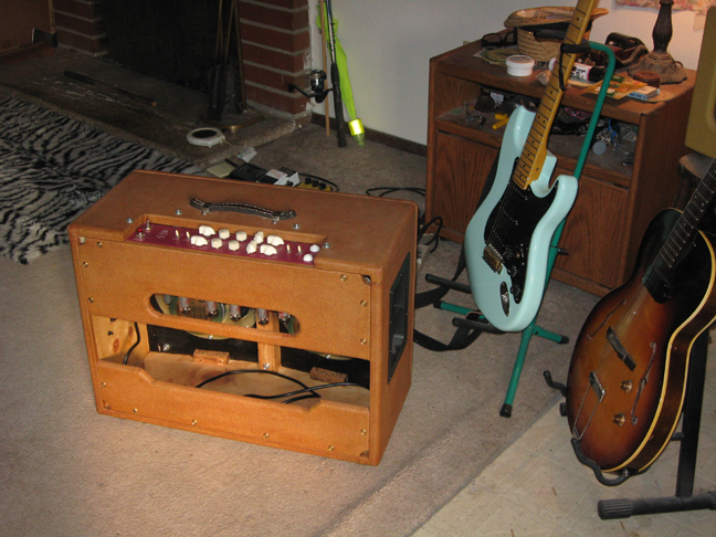
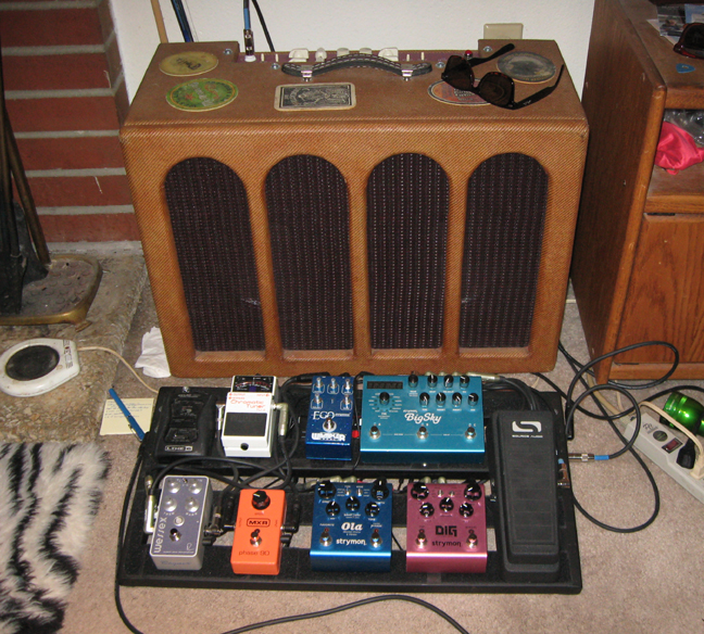
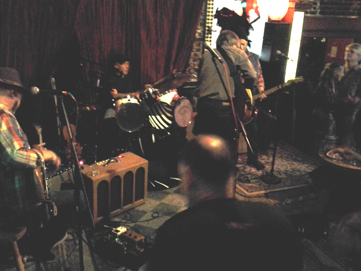
Very Nice Amp! No blocking distortion well into clipping (output overdrive). The amp is very quiet with no signal applied. It sounds exceptionally good to my ear.
If I had it to do over again from scratch, I'm not sure I needed the footswitch for alternate gain. It seems like a useful feature, but I never actually use it. The guitar has a volume knob I use instead. Maybe replacing the alternate gain knob with a Mid tone knob would make better sense. I might try using 6V6 output tubes instead of EL84's, just to see if I can tell the difference. I'm not sure 6V6's would fit in this standard size Hammond chassis in this configuration though. I'd make the cabinet an inch less deep (like in the drawing). Oh, and those 1/4 phone jacks with the plastic nuts - they are a little flimsy and the nuts can loosen over time (they do on my pedalboard). I'd use metal nut jacks that also have isolated ground connections instead.
If you can't find input jacks that have an isolated ground, then just tie the circuit ground to the chassis right near the input jacks (only), leaving the power cord earth ground connection (green wire) tied to the chassis right where it enters the chassis. Switchcraft jacks are recommended. I'm generally of the opinion that any guitar amp should have a built in reverb as a default since I never like the sound completely dry, but I really wanted to keep the control panel as simple as possible, and I think a pedalboard is the way to go for any special effects.
One thing I'd add is a line output taken from the speaker terminals. Since there is no negative feedback taken from the output, the output circuit doesn't need to be grounded, so you have usable ground isolation. all you need to do is resistively attenuate the signal. I might include a switch that gives the choice of line or mic level out. Since the output impedance of the amp is just a few ohms, the feed may not need to be balanced to be useful, especially at line level. Now that I've gotten into recording bands in bars, I've come to see the value of such a thing.
The finished amp weighs about 45lbs. Part cost for a "one-off" is probably about $1200. Labor cost would be at least that much again - probably more.
After using this amp in many jam sessions, I decided it had more treble than I wanted. It sounded too clean with a stratocaster. The 2019 Bluesman 20 watt amp I re-built after this one seems to have the perfect sound, so I decided to mod the EQ in this amp to match the EQ in the 2019 Bluesman amp. The mods are shown below in red.
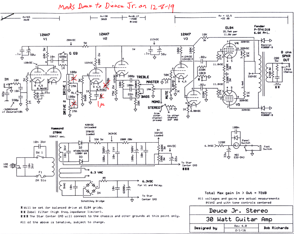
I do like the sound of this mod.
![]()