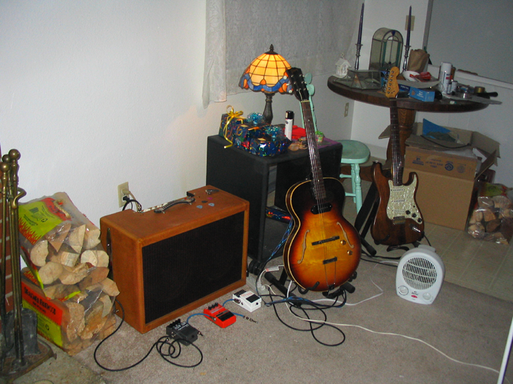

There has been another birth in the family, The Bluesman. I built a twinamp style tweed cabinet somewhat modeled after the 1959 Fender Twinamp but scaled down slightly to have 10 inch drivers instead of 12's, and built up a new chassis with a newly brewed EL34 single-ended 10 watt circuit.
It was a winner at a recent jam session.
The "twinamp" speaker configuration somehow sounds better to me than a single driver. Less in your face somehow. More ambient. It would have a significantly different off axis frequency response (and different to each ear).
Is 10 watts really enough in the real world?
Practicing in your living room at home it goes plenty loud, with very little hum or hiss. Used in a recording studio where you want the sound of an overdriven single ended output tube distortion for effect, it's plenty loud. In the real world where you may have several guitarists running on the more typical 20 - 40 watt amps, drums, and a 300 watt P.A. system you'll want at least 20 watts (from my experience playing in bars). Since this amp weighs about half of what my 60 watt Stereo "Deuce" amp weighs, I take this amp for practice sessions and smaller parties, and the bigger "Deuce" amp for the bigger parties/clubs or outdoor gigs. Since the Line Out circuit has no connection to Ground, this amp can be used as a preamp for a much more powerful amp, thereby giving you an excellent distortion sound, at the much higher levels.
Any balanced (symetrical) high negative feedback circuit topology (tubes or transistors) often generates more of the odd harmonic distortion products than even. And, more higher order harmanic distortion products in general, which are less pleasantly musically related to the fundamental frequencies coming from the guitar. The first harmonic is the fundamental frequency by definition - the note you played. The second harmonic is the first "even" harmonic, and is the same note one octave higher. It's presence will enhance anything. It's always a good thing. The third harmonic (which is the first "odd" harmonic) is another half octave higher in frequency, which forms a "major" chord with the fundamental and 2nd harmonic product. That is not desirable when the song is in a minor key. The higher harmonics are hit and miss as to whether they are pleasantly musically related to the fundamental (the note you played). An accumulation of higher order harmonics means an accumulation of "notes" that are not pleasantly musically related to the fundamental. They cause more of a fizzle type sound. Sometimes a "fingernails on a blackboard scratchy sound... Also, the further away in frequency a distortion product is from the fundamental, the less it will be "masked" by the fundamental.
![]()
The best sounding distortion in when you have significant 2nd harmonic product generation, and a qicker rolloff of the higher order harmonic distortion products. If you're a heavy metal guy, you might actually want the higher order harmonics. This amp will give you plenty of those if you turn up the input level enough.
A single-ended topology with no negative feedback, will generate a second harmonic distortion product that is stronger than the third harmonic, when run clean, or when over driven into much more obvious distortion.
I've been told by the tube gurus that paralleling tubes in the SE topology doesn't sound as "musical". I'm pretty suspicious of that statement. Most of what I've found on the web while researching all this, is written by people who don't have all the facts and/or don't realize all the different interactions and variables speak. There are many claims from experiments that were riddled with variables that weren't addressed. There's also the strategically unbalanced push-pull which would give you about 35 watts out of a pair of EL34's or 6L6's. That should be a close second. For this amp though, I wanted the highest potential of musicality of distortion, with no compromise what so ever that I know of. If I need more power, I can run the Line Out to another amp or P.A. system for a boost.
The best possible vintage blues style tube distortion in a package that is fun and practical. Able to run relatively clean to usable levels as well (in the home anyway). High on second harmonic, fast rolloff of higher order (frequency) harmonic distortion products, a maximally gradual and complex overdrive transition, the projection of the twinamp style speaker configuration and open back cabinet, very few knobs or switches on the panel, at least ten watts, big enough to be warmth but small and light enough to drag around to jam sessions without getting too annoyed, no hum, minimal noise, the line-out circuit, good Rf filtering at the input and AC, very cool look.
The EL34 has a great reputation and will always be easily available. With two of the highly efficient vintage reissue P10-R, (from Antique Electronics Inc.), the acoustic power is quite impressive. The first 5 watts are relatively clean for a guitar amp, unless you overdrive and then attenuate the 12AX7 stage using the Master volume control. At a recent jam with this amp in a living room of a medium sized house, the volume knobs were no where near all the way up. It went way louder than I wanted, and sounded excellent at the level I did want. I set the input level control so the 12AX7 "fullwave saturator" stage (as I call it) is just slightly distorting, then adjust the master volume for how loud I want that.
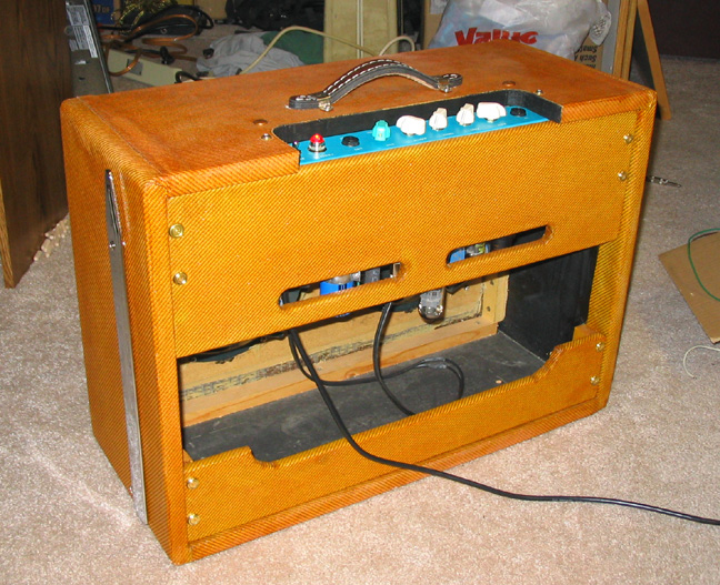
The cabinet is all solid pine, covered with tweed bought from Antique Electronics in AZ. I read somewhere that Eric prefers the sound of solid pine (The 1950's era Fender amps were allegedly all made out of solid pine). The internal bracing is all solid oak, for robustness.
Since digital reverbs, compressors and etc. are so abundant, and specific to each guitarists tastes, I didn't see any reason to include any sound effect processing in the amp cabinet. Just pre and post volume, and bass and treble. I had a Boss SE-70 stereo digital guitar effects processor from the early-mid 1990's that sounded exceptional. More recently I've built up two pedal boards. Those pedals keep getting better and better.
The front end circuit (6SJ7 pentode) is similar to the Octal Fatness circuit as well as many other amps from the early tweed era (1950s) Fender and Gibson.
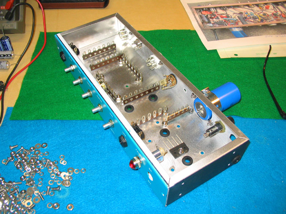
This above photo shows most of the lug strips (not all) that were needed. The bridge rectifier shown above is for the 6.3VDC filament voltage. It's bolted down to the chassis for heat sinking, directly under where the power transformer will be mounted. Yes, I'm running the filaments on DC, to minimise hum.
3 Weeks Later:
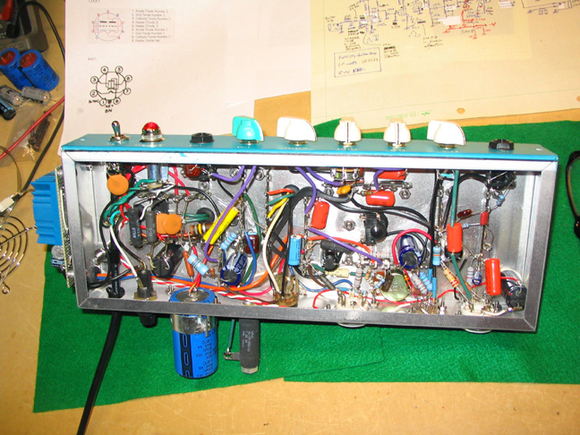
The high current electromagnetic field producing power supply and output circuit are as far from the high impedance input stage as is practical (a must). All grounds return to a "star center" circuit ground point., which is 100 ohms off earth ground/third prong of the AC plug and chassis (100 ohm bypassed with a 2nF mica cap). The AC cord has an additional clamp inside the chassis, in case someone trips over it. The regular "strain relief" grommet thing is a bit meager by itself.
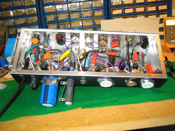
The 6SJ7 pentode tube (not in current production) comes in either black metal or glass. Both are excellent. It was the input tube of many guitar amps in the late 1940s Including the very first Fender tweed amp called the Dual-Professional, later renamed the Super. The 6SJ7 seems to contribute a sort of "woody" quality to the coloration. Heavy on the second harmonic, at the expense of intermodulation distortion (you need the right balance). This input tube also acts as a microphone to some extent, picking up vibrations, both radiated and conducted, from the speakers. This is a form of feedback, and contributes a slight but complex resonant coloration (not necessarily desireable but seems to be). The 12AX7 can be independently overdriven by manipulating the input level control and the master volume control. The EL34 contributes an early-Marshall soft crunch at high levels, but with the better harmonic distortion spectrum shape (more second harmonic and less higher order harmonics).
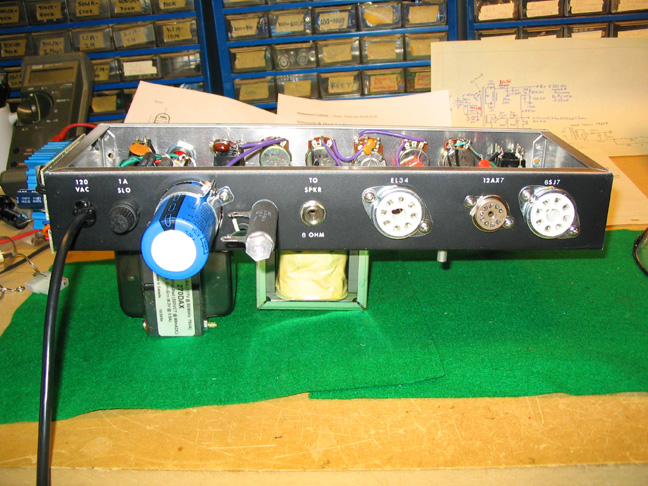
You can see the bias pot for the EL34 protruding south, just to the right of the EL34 tube socket (above). It's wise to locate it as close to the control grid of the EL34 as is practical since it's a high impedance node that could be susceptible to picking up stray fields. You NEVER want to mess with this pot unless you know what you are doing, and have test equipment hooked up, or you could blow up several expensive parts. Ceramic sockets move the heat from the tube into the chassis the quickest (a good thing). There's a jack for a fan to be hooked up to the DC filament supply. Since the EL34 is biased ACTUAL class A, it dissipates almost 24 watts continuously, signal or not. Since it's mounted upside down, I felt that a fan would be a good idea (extend tube life substantially).
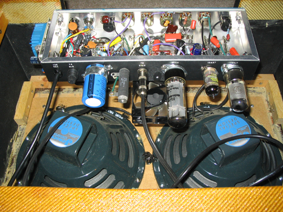
You can see the position of the fan above. By running a 12 volt computer fan on 6.3VDC, it's a lot quieter. The fan stalls at about 5V. It's shock mounted to reduce noise also (rubber grommets).
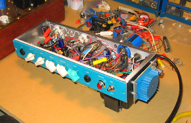
On the right hand end of the chassis (above) is the turbo unit (EL34 bias supply toroid). I didn't want to lose ANY of the B+ to the bias function (roughly 20 volts). It's a squared term in the power formula, so makes a big difference in final watts out. It's the same one I used on my 5 watt "Fat Mama" guitar amp, where I used "cathode bias" on a 6V6GT SE output tube. .
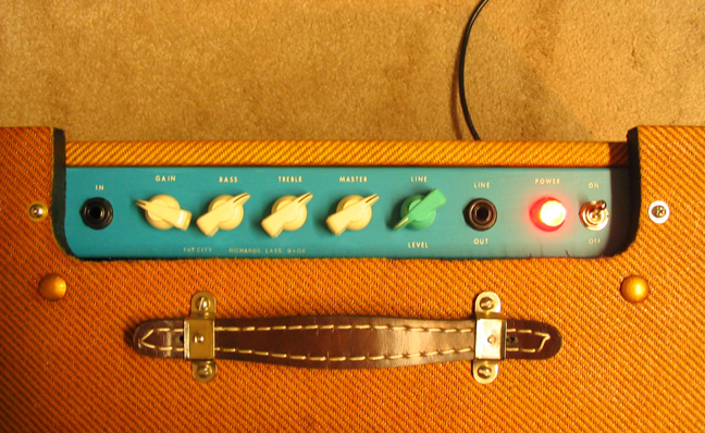
A simple panel is minimally distracting when you want to stay rooted in the musically creative part of your brain.
I had the panel paint color custom mixed. I call it caribbean blue.
The Line Out can be used to drive a second more powerful amp, a P.A. system or whatever. The Line Out signal is taken right off either the speaker. It has 5 volt zener limiting and an Rf filter as well (to minimize it's ability to damage an input stage by overdriving it). This way, you get the great sound of a single ended topology, and if needed you can jack up the level with a bigger amp, using this amp as a "preamp".
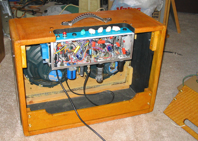
You just remove the upper rear panel to access the innerds. I bought the Fender tilt back arms for the sides, so I can tilt the amp back for better sound projection. After using them at a jam, I decide to get rid of them. Not really stable enough on a hard floor.
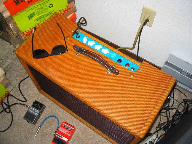
This amp also makes a nice seat for the guitarist at a jam when things are really cramped. Or a place to set things. I didn't realize how dark the amber shellac would be on the standard tweed covering. I then tried to remove/reduce it with rubbing alcohol on one of those red mechanics rags that was handy. The red dye in the rag dissolved and tinted the amber more redish, which I like afterall.
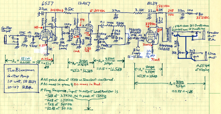
Notice that the secondary of the output transformer has no connection to Ground. This is so the line out can drive other bigger amps without there being a ground loop issue (potential hum problem).
The output transformer is wired such that the 16 ohm tap is driving the 8 ohm speaker load. I wanted max voltage swing and actually preferred to have some dynamic range compression, which will make the amp sound mellower, and give it more sustain.
In the upper-right area of the schematic, you can see the 100 ohm resistor on the B+ feed. That gives me the amount of "sag" that I might want, which most people seem to think requires the use of a tube type rectifier. Only a fool would actually use a tube type rectifier. It's a sales gimmick. "Sag" is strictly a function of the on-resistance of the rectifier tube working with the source current capability (limited by the DCR of the high voltage winding of the transformer) and the filter cap just down stream from it (22uF). That's what the rest of the amp circuit sees, and reacts to. The amp circuit has no way of knowing whether the sag is from an RC or a tube resistance working against its downstram filter cap, since everything above about 70HZ is filtered out by the 22uF cap. The lowest note on a guitar is 80 HZ.
There's a belief that using all very expensive Teflon or styrene caps ($35 each) and very expensive custom transformers (>$100), and even Teflon insulated silver wire will sound better. One boutique amp manufacturer even offers a gold plated chassis. These are in my opinion all sales gimmicks for the rich fool. Fancy transformers could actually sound worse depending on impedance's and saturation rates. Regular polypropylene caps ("orange drop") are plenty good for this and any hi-fi applications in my opinion. They are only a few bucks each. Metal film resistors are the lowest noise types, they're very cheap, and should be used in the front end and 12AX7 stage wherever the value is over about 5Kohms, for minimal hiss noise. The rest of the resistors should be metal oxide for the sake of reliability (they handle overloads the best). Wirewound is fine in the power supply. I bought all the parts at Antique Electronics Inc., or Digikey, or Mouser. For Rf filtering, ceramic and mica go the highest in frequency before fizzling out. Mica is the better one when the value is available.They are also very cheap. I chose to use higher than needed voltage ratings on many of the caps just in case elements in a tube were to short out and cause much higher voltage to occur temporarily. That actually happened in one of my amps. Tubes are funky, especially the old ones, and will occasionally fuck up (short out internally).
The original tone circuit, a fender "stack" seemed a bit meager in actual use (fairly limited range) so I decided to go with a Duncan version of the Fender e-type tone topology which looked good in the Duncan analysis program below (it's a freebie that plots the curves - avail. on the web).
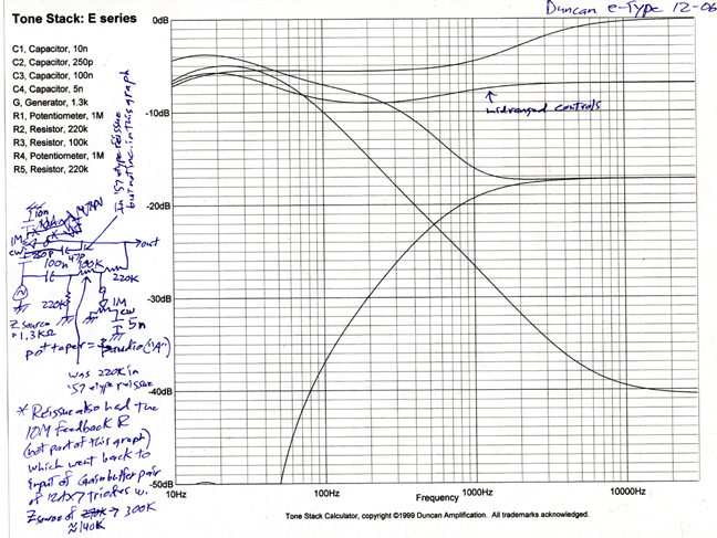
This e-type circuit is very similar to the circuit in a 1957 Fender e-type Twinamp; the one Eric Clapton has been using exclusively since about 2000. I like it. It's also less lossy than most topologies, which was a critical issue in this circuit. The signal coming out of the tone stack was barely large enough to drive the EL34 into clipping and get the full 10 watts.
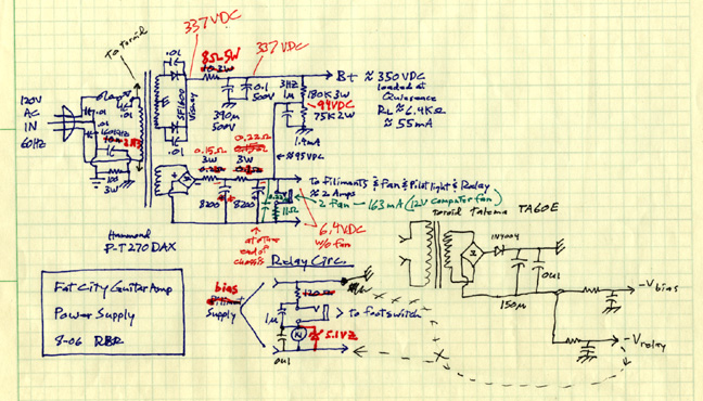
I never hooked up the footswitch/relay circuit. I can add it later if I decide I would actually use it. The powersupply circuit in the lower right of the above power supply schematic is the preliminary bias supply for the EL34. It's nothing special. The additional diode after the bridge is redundant and not used. It's such a simple and basic circuit I was too lazy to draw it out beyond that. I just built it.
It turns out to only put out about 8 watts rms into my 10 ohm load resistor (so approximately 10 watts into the 8 ohm load of the speaker driver), but it's got the tone control circuit Eric Clapton has in his amp, and a real nice overdrive distortion sound. The Jensen P10R speakers have a long reputation of being a classic rock/blues sound. It's the exact same driver that in used in the 1959 Fender Bassman, which many guitarists feel is one of the best sounding guitar amps of all time. I hope this inspires other hobbyists. It was a fun project. When I played Crossroads, by the Cream thru it (1968 Wheels of Fire version), I knew I had a winner.
Happy Jamming!
![]()