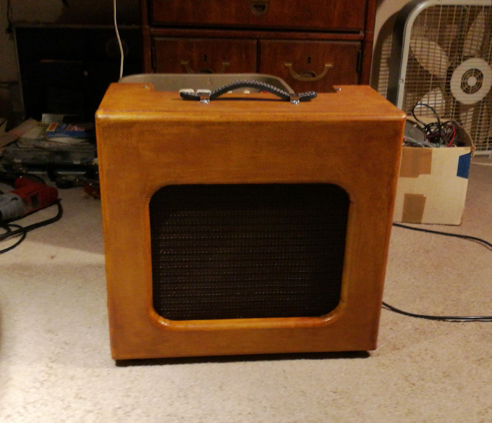
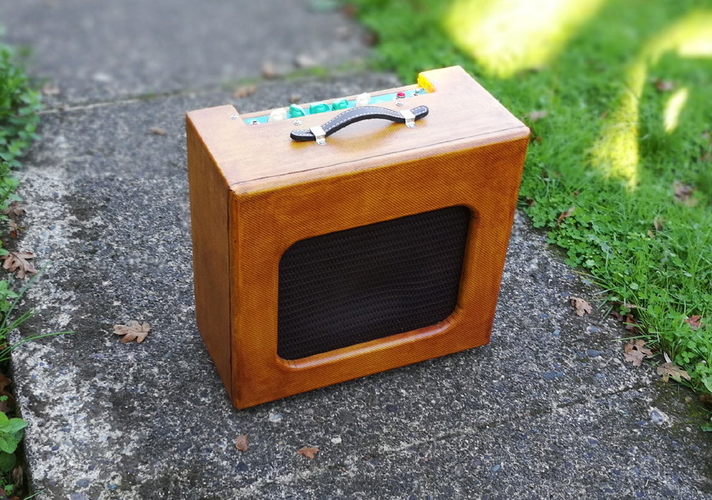
The Bluesman Dynaflow
18W Mono Guitar Amp Project
by Bob Richards 12 9 23

The goal with this amp was to make the physically smallest
amp that should be able to keep up with a typical rock/blues band in a typical
bar venue. Also to use only the most conventional tube types. I've noticed
that most of the bands I see in the Portland area use the Fender Deluxe Reverb,
or an approx. equivalent. Small enough to be practical to carry in and out
of venues, but powerful enough to do the job well in most cases. The stages
are usually cramped, and carrying a big heavy amp is less fun as you get older.
So here's my version of a Fender Deluxe guitar amp.
Fender pushes their 6V6GT output tubes pretty far beyond the
max B+ voltage ratings, according to the "official" tube manuals,
in order to get the 20watt output power rating. I did that in one of my other
amps, no problem (with JJ brand 6V6's). In this amp, I chose to go with 18
watts output power, because I needed a 10 watt power resistor for part of
the RC power supply filtering, and that's the value I happened to have (180R).
I exceed the max voltage rating for the 6V6's, but not by as much as the Fender
Deluxe.
I've heard that due to the popularity of the Fender Deluxe
amp, todays tube manufacturers are designing their 6V6GT tubes to handle the
higher B+ voltage.
Here's the final circuit I came up
with. I initially tried using a Dumble front end, but it had more
gain than I wanted, so I switched it back tot he more typical R values (same
as the Fender Deluxe and many others). Even then I had to throw away a bunch
of gain feeding the master volume control. I must admit that I got lazy and
didn't do all the math I could have. If I knew I'd have this much gain, I
would have used a James tone control circuit instead of the more typical "tone
stack" circuit. The James (a passive Baxandall approach) gives significantly
better range for each tone control, but is about 10dB more lossy than the
tone stack topology. Having said that, this is still a great amp.
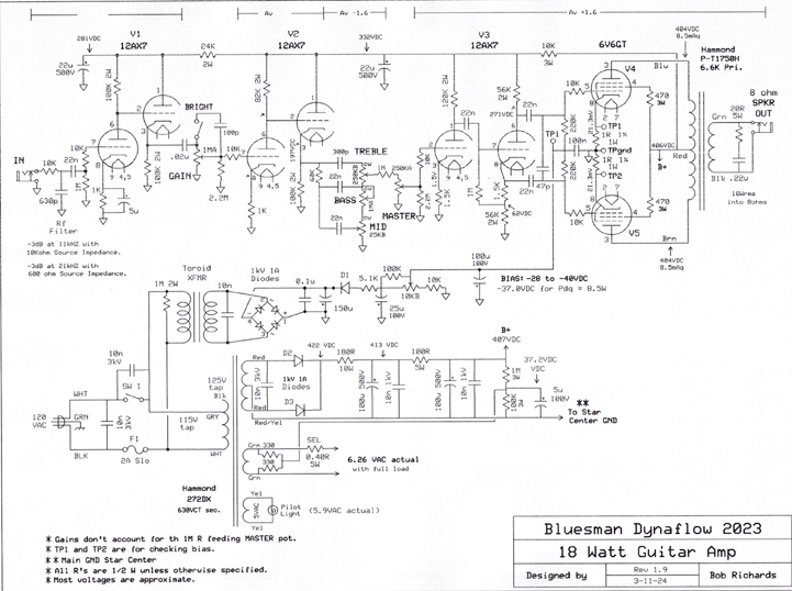
For a Tone Stack, I wanted to have Bass, Mid and Treble. The
difference between the Fender and Marshall stacks appeared to be "academic".
Slight topology difference, perhaps to avoid copyright issues, but not much
operational difference. This is a slight variation of a Marshal Tone Stack.
The Phase Splitter (the 3rd 12AX7) is a "Cathodyne"
topology, which could be argued to be less high end (compared to the differential
("longtail")or Paraphase splitters), but the asymetry at higher
frequencies produced by the output Z differential, creates a slight distortion
that is arguably desireable for a guitar amp. It's what is used in the 1957
Fender Twinamp that Eric Clapton has been using for the last at least 25 years.
I've tried all 3 phase splitter circuits in my various amps, and they all
work fine. This one MIGHT sound slightly "juicier", but there are
too many other variables between the different amps for me to make any real
claim here. My personal favorite might be the Paraphase, because it has a
pot that adjusts the exact amount of asymetry between the two outputs, which
shapes the distortion spectrum better (specifically, a slight asymetry brings
the 2nd harmonic distortion product up in amplitude, which sounds more "organic"
or "natural". Less metalic, less "fingernails on a blackboard".
The output stage is is a Push-Pull 6V6GT circuit, with a fixed
bias arrangement. Cathode bias would have been fine too, but I already had
the power tranny I would use (which costs over $100), which has less secondary
voltage than I wanted, and I already had the bias supply built (pulled from
another amp I built that didn't measure up), so I went with the fixed bias
route to get the full 18 watts. If I'd gone with Cathode bias using this power
tranny, I'd have lost 20-30 volts of B+ across the cathode bias resistors,
and ended up with something like 10 watts final output. Voltage is a squared
term in the power formula, so a small loss in B+ will give you a big loss
in output watts.

One reliability issue in tube type output stages of all guitar
amps is where the impedance of the speaker goes way up at frequencies above
the audio frequency range (typically above about 12kHZ depending on the exact
speaker driver). When you overdrive the output stage, the clipped waveform
generates energy above the audio frequency range. The output transformer becomes
barely loaded at these higher frequencies, and can turn into a bit of a spark
coil. Many amp circuits put reversed bias diodes off the plates of the output
tubes to combat this.
When the output tranny is effectively unloaded, it can turn
into a spark coil, and cause arcing in the output tubes and/or in the output
tube sockets. Rather than using diodes off the 6V6 plates to limit this, I
put a series R and C across the speaker driver, so the impedance as seen by
the ouput tranny is always limited to a somewhat safe amount. Since this RC
combo doesn't do anything below about 15kHZ, it does no harm and makes the
amp significantly more reliable when pushed to it's limits. The Fender Deluxe
ignores this issue all together, so maybe not necessary in a low power amp.
The power supply is all pretty straight forward. I don't like
using chokes because the are physically large, they add significant weight,
and they're really not needed now that higher value electrolytic capacitors
are easily available (large value electrolytic capacitors weren't always available
and/or cost effective back in the 1960's and 70's). But a two stage RC filter
does get rid of a significant amount of potential B+, so you need to take
that into acount when choosing the power tranny secondary voltages. This circuit
loses about 15 volts there, while a choke might only lose a few volts. The
Bleeder resitors (to help discharge the filter caps when the unit is turned
off) also acts as a voltage divider that is used to "float" the
filiment supply at 37 volts (in this case), to reduce the amount of potential
issue with the cathode to heater max voltage spec. I exceed that spec to some
degree, but most, if not all Fender, Marshall, and most other amps don't seem
to care about exceeding that spec by quite a bit in their designs. It's especially
important when using cathode follower topologies. I do this for improved reliability.
Rf (Radio Frequency) and Digital Noise...
When supersonic energy is delivered to the input of the amp (with the
guitar acting as an antenna, and/or a pedal board with digital processing
and/or switchmode power supply), at some point in the circuit that energy
will get "demodulated" or "detected" and generate random
audio frequency noise and Intermodulation Distortion (which generates sum
and difference frequency products), which are not musically related to any
notes you're playing on the guitar. Hence, the RC low pass filter at the input
jack where the guitar plugs in. This Rf energy can also come in on the AC
power cord. Especially if you are in a venue that has light dimmers, which
are usually switch mode circuits that generate lots of Rf endergy. Hence the
0.01uF 3kV ceramic cap across the AC line connector. Most amps I've seen don't
bother with either of these Rf reducing methods. I think they are significant
and should be addressed.
One thing that is common to all the amps I've designed, is
that they don't use any distortion reducing negative feedback (like the Vox
ACXX amps), from the output to an earlier stage. This distortion reducing
feedback causes the amp to "clip" during overdrive with sharper
corners, which means the distortion products go way further out in frequency,
and happen significantly more abruptly when the amp is over driven. I
prefer an overdrive that happens gradually, for a better bluesy sound.
Using cathode follower buffers in the 1st and 2nd stages helps keep the amp
very clean (low distortion) unless you specifically adjust the two gain pots
to overdrive the 2nd stage, or the final output stages after the Master volume
pot.
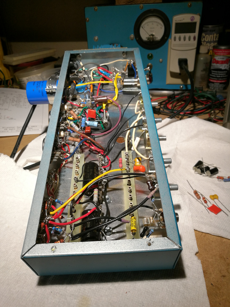
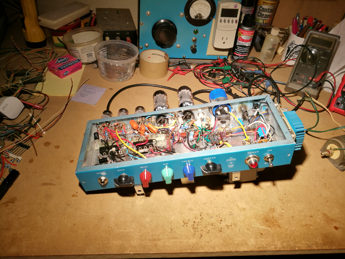
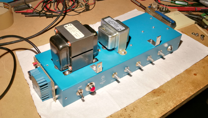
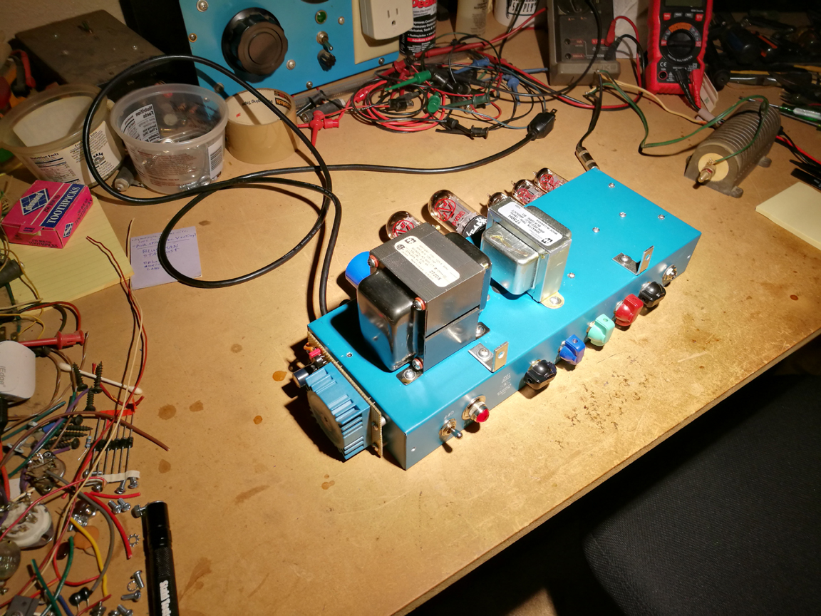
Here are some pictures I took during the build process:
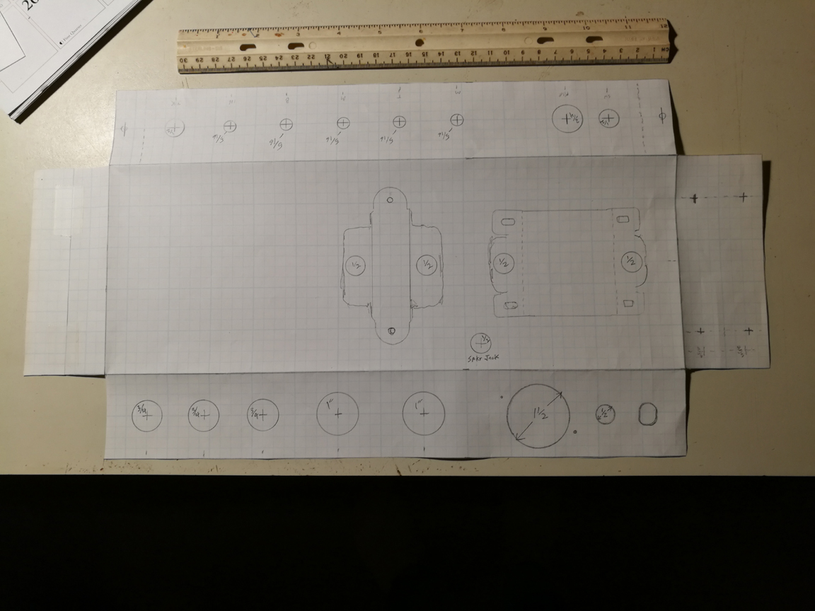
First I plan the physical arrangement of everything on graph
paper (oldschool and proud of it). That becomes a template for fabrication
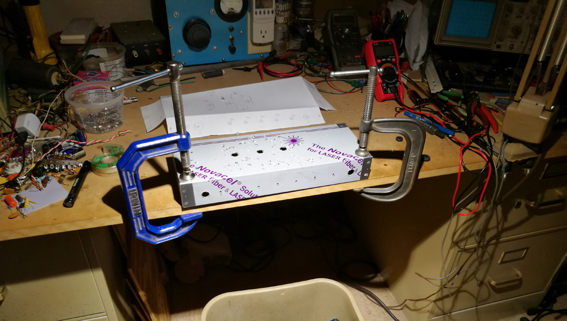
of the aluminum chassis. I scotch tape it onto the chassis, center punch all
the holes that I remembered to include on the template (I always forget a
few till after the paint job). Then pull off the paper template, drill all
the holes to proper sizes. wash the chassis with hot water and dish soap,
then sand the outside with fine grit sandpaper (500ish) or steel wool . Then
wash it again with dish soap real good, dry it thoroughly, then spray paint
the outside with Aluminum Primer (most primers don't work worth a shit - the
primer must specifically say "Aluminum Primer". Then color paint
twice, then do the dry transfer lettering (my preference on one-offs), then
at least two coats of matt finish clear spray to protect the fragile dry transfer
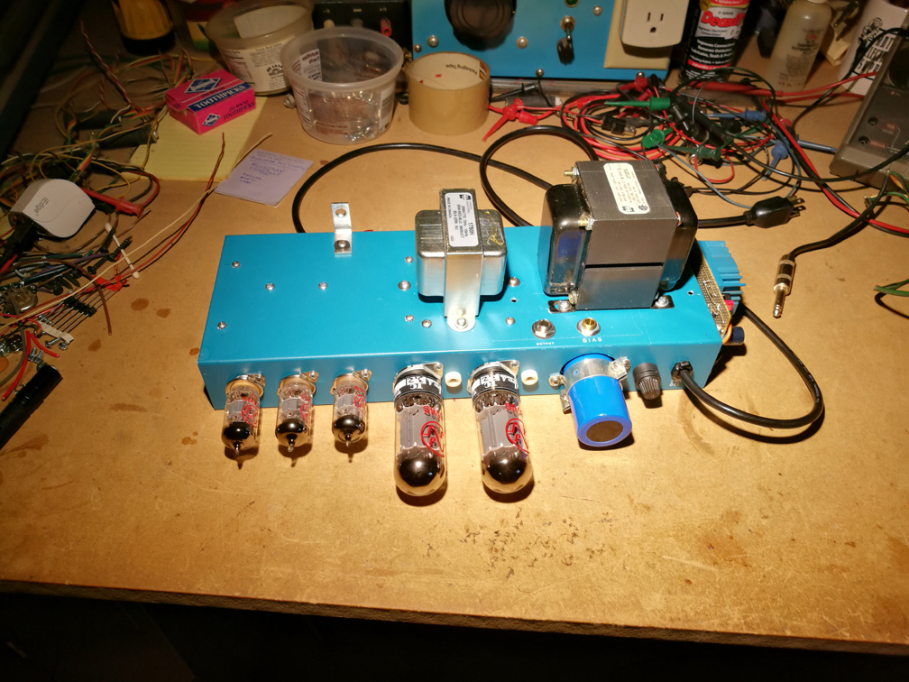
lettering. Then it's time to populate the chassis, with all the crap.
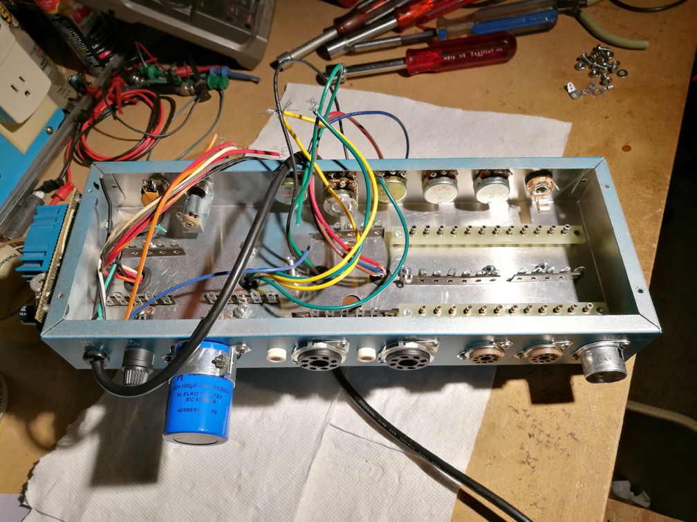
I always guess at how many lug strips to mount in the chassis,
rather than having an intensive pre-plan showing where every single part goes
(the professional way). I like the challenge of guessing (since I've got alot
of experience with this), and I'm lazy. Also because I experiment as I go,
and I often choose to change things before I call an amp done.
I usually start the wiring process with the power supply. then
the front end stages. Then the phase splitter, then the output stage.
Whatever devices (transformers) have the longest most in-the-way
wires get wired early on.
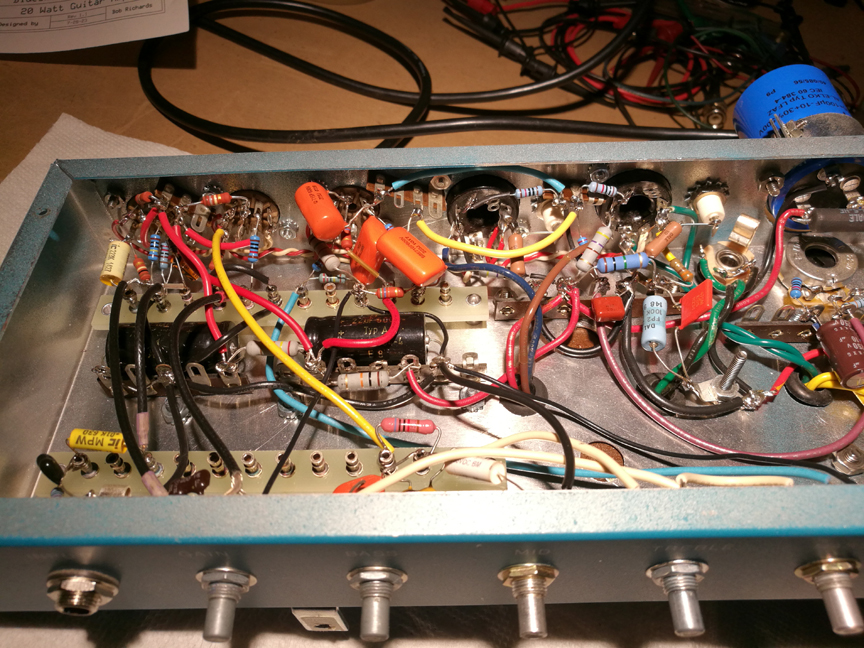
The above photos are actually obsolete. I later rotated the
output tranny 90 degrees so its magnetic field would be less interactive with
the power tranny.
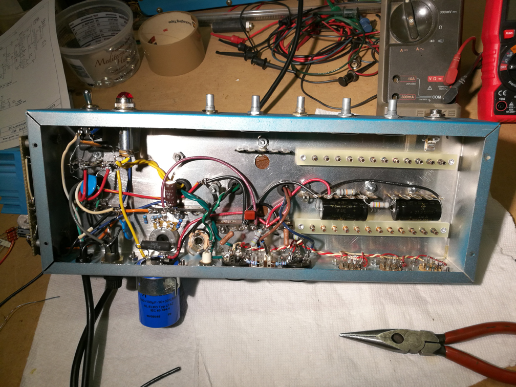
The chassis is held into the cabinet by steel bolts at each
end, and then there's also angle irons (in photo above) for further support.
The one mistake I made with this amp (very embarrasing) is
that when I went to install the finished chassis into the cabinet, there was
no way for me to get my hand in there to put a nut on the screw for one of
the angle irons (the one by the power tranny). You try to predict every part
of the build process, so you can optimize everything, but sometimes you overlook
something, and then you get to learn... what to do better next time. I should
have positioned the angle irons so I could get at them on the bottom side
in the cabinet. Oh well...
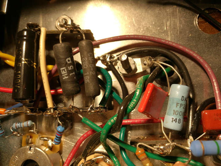
I like to somewhat "calibrate" the heater voltage
so it's very close to 6.3 VAC fully loaded.
Most amps seem to run that pretty high IMO, which ages the
tubes faster. Hence the above power resistors.
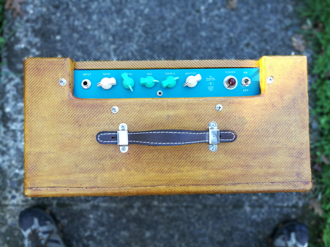
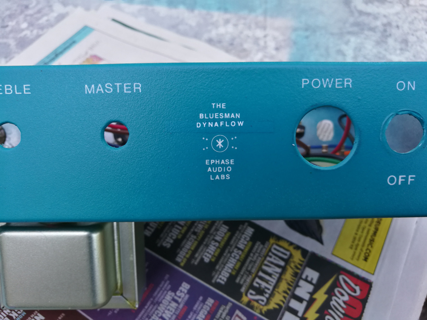
I'm a huge fan of a simple control panel, in case you want
to adjust something in the middle of a jam. It's much less distracting.
Since I'm a pedal board guy, I don't bother puting Tremolo
and/or Reverb in any of my amps. All my guitar friends are also pedal board
guys or gals.
Newer juicier pedals come out all the time. Built in effects
can end up redundant, and clutter up the control panel.
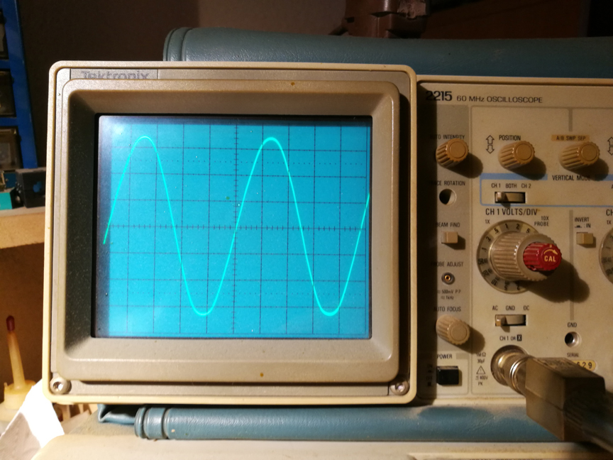
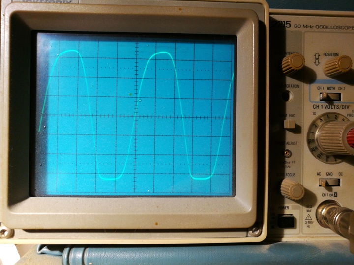
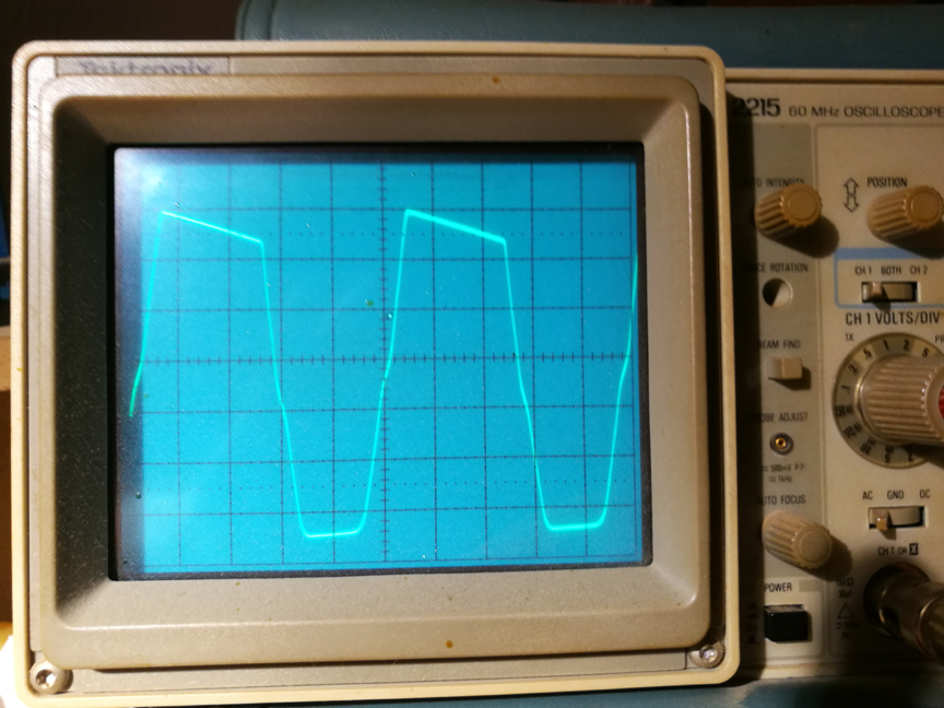
Above are some waveforms: Just short of overdrive on the left
(plenty clean). Somewhat over driven in the middle. WAY overdriven on the
right.
Don't read too much into these photos, since this is just one
frequency (around 1kHZ) and there are many other variables in the real world
sitch.
These photos are with the amp driving into a 10 ohm 100 watt
Load resistor, rather than an actual speaker driver; another very significant
variable.
The above photos are overdrive of the output stage. There's
also the option of over-driving only the 2nd 12AX7 stage by setting the Input
Gain and Master volume controls to do that.
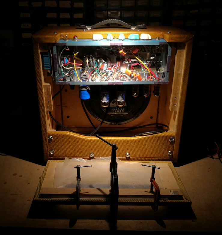
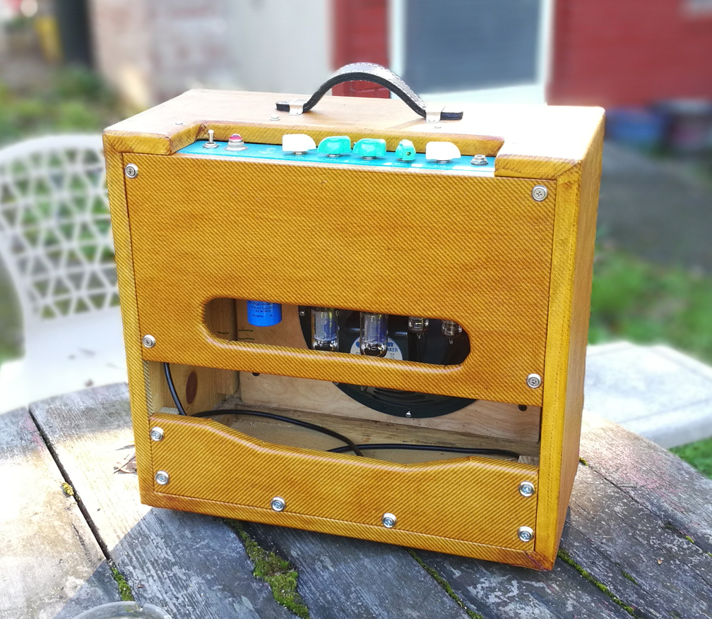
The tweed covering came loose at the edge due to shitty spray
contact cement, so I had to re-glue it down. I clamp it with a scrap board
and wax paper.
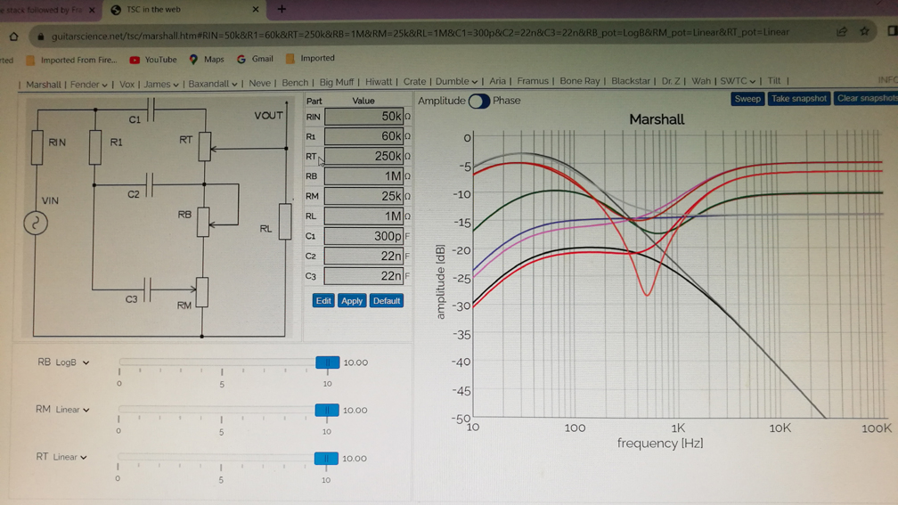
On the right is an approximation of what the tone controls
do, using the TSC free download program from the web.
That's about it. Now I just need to see how it integrates into
a full band situation. This is a very basic amp. Nothing particularly fancy.
The speaker driver is a Jensen P10R; the same driver that is
used in the coveted 1959 Fender Bassman amp. A classic rock/blues sound.
The Alnico magnet helps keep the weight down, and allegedly
has a softer over-drive charactoristic, compared to ceramic magnet drivers.
It sounds real good in my living room at home. No significant
hum or hiss-noise issue at all.