9-17-09
(c) copyright 2009, Robert B. Richards
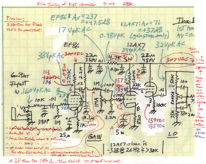
There was a consistency in the "fizzle" of the distortion that seemed annoying. I felt that I'd heard better.
I started looking at circuits, and particularly at the headroom in the various stages of some known very good amps. I looked at the '57 Fender Twinamp that Eric Clapton has been using for the last decade, also the GA-40 Les Paul amp that sounded pretty darn good when I tried one once. Also my Fat Mama amp that is very similar to the "Octal Fatness" amp on the web (designed by Jim Morrossy I think). The good amps had between 235 volts and 265 volts feeding the 12AX7 distorter circuit. I had mine up at 307 volts. I figured that by reducing the B+ to just that section, I'd get a more gradual distortion with more apparent compression. I also wanted to make sure that clipping was dominated by saturation rather than cutoff, since I told that that would have "a more balsy sound". I made a copy of the part of the preamp circuit that I would be modding, and started brainstorming what should be looked at.
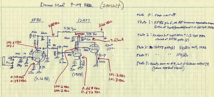
I settled on a circuit to try. I changed the power supply to only the 12AX7 stage, leaving the feed for the EF86 pentode front end as it was. 200VDC may be a bit low, but I wanted to experience it first hand.
Well, the distortion sound was a bit too sloppy, delicate, fizzled, and frazzled sounding, and it didn't quite cut it for me. I'm not really a big fan of distortion per se, so it's got to be the best for me to like it at all. Below are the waveforms.
Note: Looking at only the waveforms tells a pretty limited story, but that's what I've got. Use of a specrum anayzer would be every bit as important, but would also be limited. The real test is playing guitar through it for about an hour, "feeling out" various distortion levels and tone control variations. I did both.
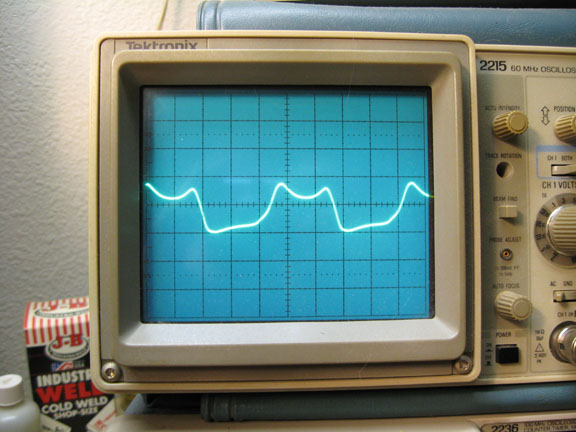
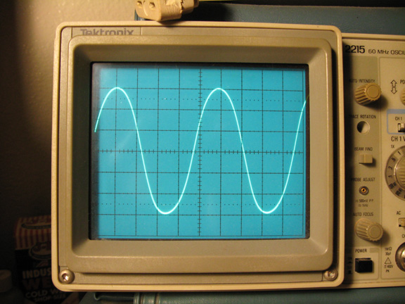
Photo 1, EF86 (JJ EF806S actually) front end pentode plate just starting to show visable distortion (vertical scale numbers are written on schematics) - all tests done at 1kHZ:
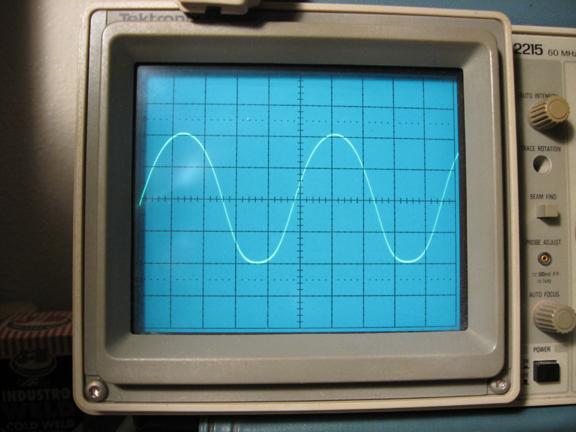
Photo 2, as above but driven harder.
Note: The 12AX7 stages are highly likely to be well clipped before the EF86 stage will clip in most situations.
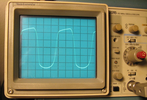
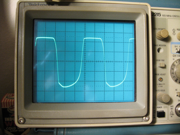
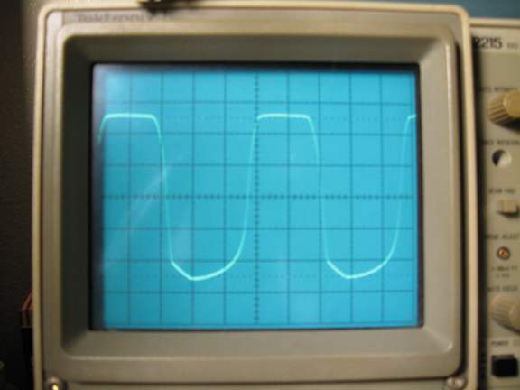
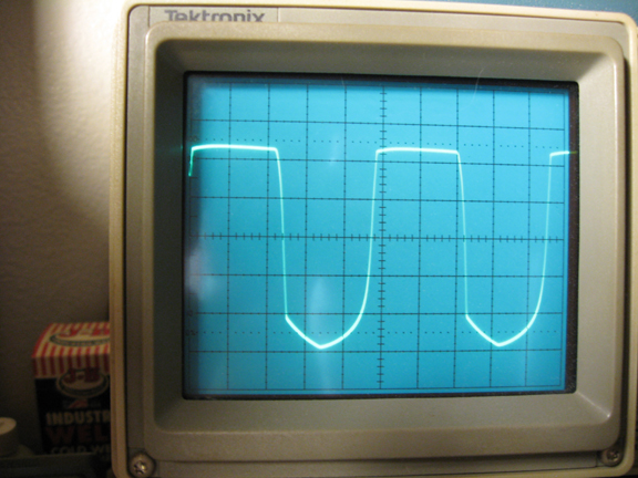
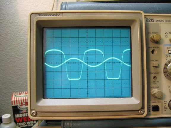
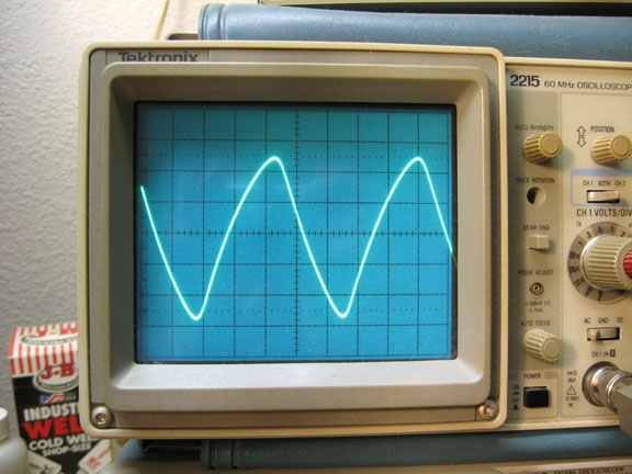
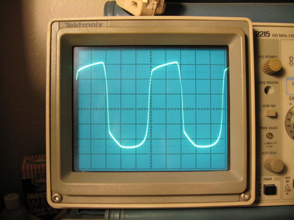
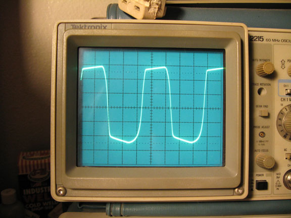
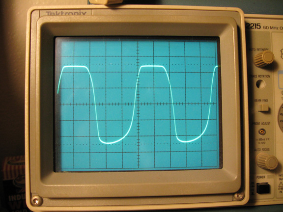
Photo 3, 12AX7 section just short of visable distortion:
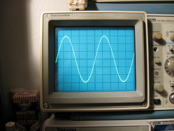
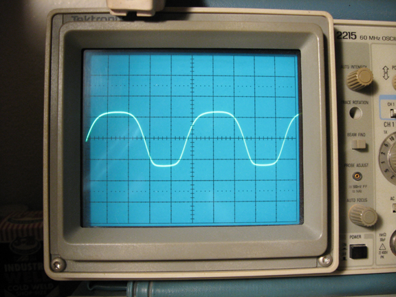
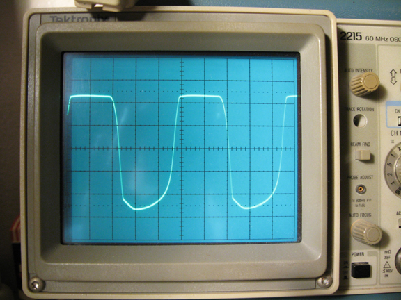
Photo 4, as above but a little more drive:
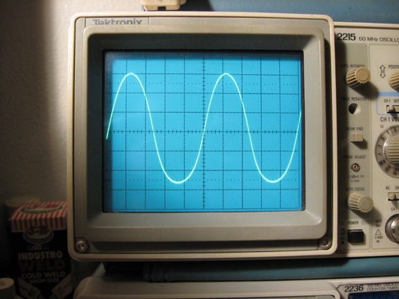
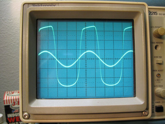
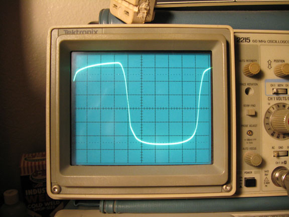
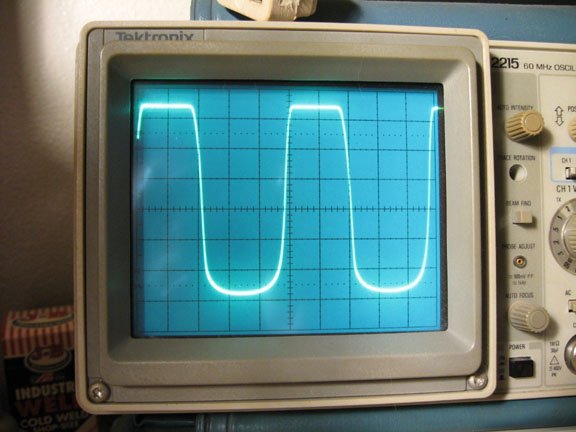
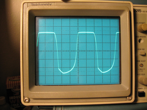
Photo 5, still further driven into distortion:
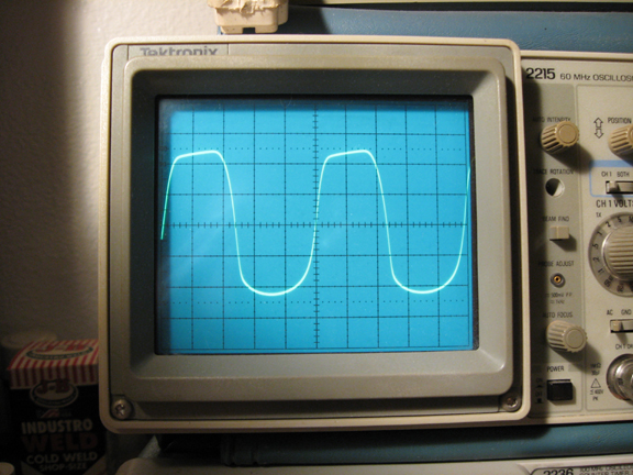
The clipping of the positive half cycle is likely due to the follower loading as it starts to draw some grid current. Without the 33Kohm resistor on the grid of the follower, that angle might be shorter term, as it was in previous tests.
Well, after getting convinced that it was actually better sounding before the above mod, I decided to put the 12AX7 stage on an average of the B+ levels of the three best sounding amps (to my ear) that I know of. This time I not only changed the B+ to the 12AX7 stage, but cut in half the cap on the pentode screen grid to match my Fat Mama circuit, and deleated all together the cathode bypass cap on the 12AX7. I had more gain than I wanted, and by letting the front end do more of the gain, I'd have less hiss at the final output. Pulling that cap off the 12AX7 reduced its gain from about 70 to about 45, and I barely even noticed the difference when I went to play the guitar through it.
Below are the waveforms.
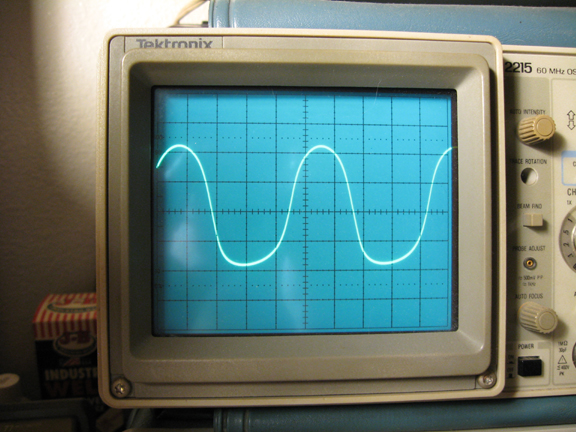
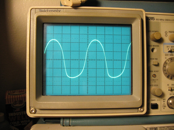
Photo 1, EF86 front end plate starting to show visable distortion:
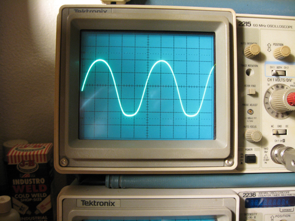
Photo 2, EF86 driven a little harder:
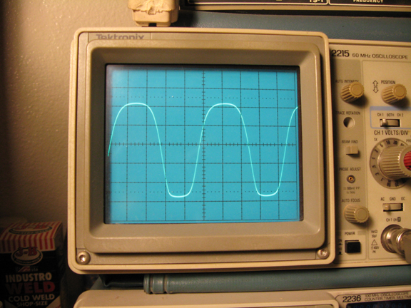
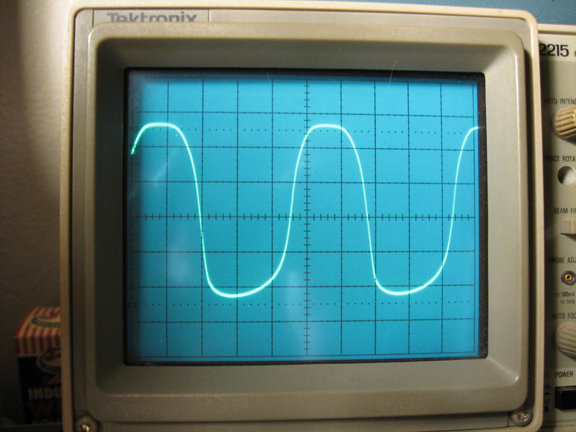
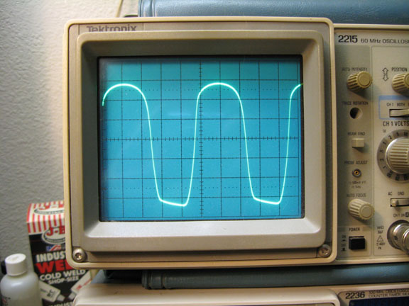
Photo 3, 12AX7 section at edge of distortion (plate of voltage gain triode):
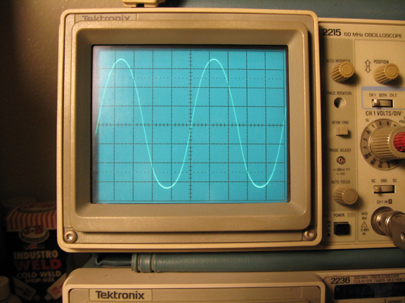
Photo 4, as above but more drive:
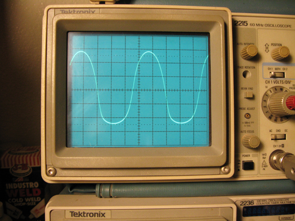
Photo 5, as above but still more drive:
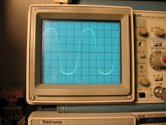
Photo 6, more drive still:
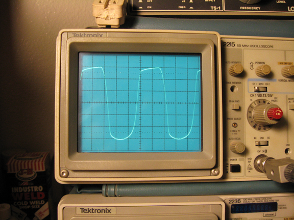
Photo 7, as above, but looked at from the cathode of the direct coupled follower, the actual output of that 12AX7 distortion section:
Conclusion:
When the B+ for the 12AX7 stage was at 300ish volts, the distortion seemed slightly "hard". Something was too consistent in the treble part of the sound. When the B+ was around 200volts, there wasn't much clean headroom, and it was too all over the place somehow, sloppy and drippy, even when I tried to limit the input drive. At around 250 volts, it seems to have about the right amount of stiffness and bubble, without losing too much of the cream or having too much noticable fizzle consistency. I may be happiest here in 250 land. If all other things were equal, and they're not, this would be likely to be slightly stiffer than the Fender Twinamp that Eric uses (but he has 6L6 poweramp tubes, which may compensate somewhat). He's down at 235 VDC. When I pulled the bypass cap off the 12AX7 cathode resistor, the gain of that stage went down, which I wanted, but it would also make the output impedance at the plate a bit whimpier. When the plate is driven positive, the loading effect of the follower grid goes up significantly, thereby modifying the waveshape in a way that is desireable for distortion generation, because of it's lack of consistency and high frequency content. I theorize that by putting that 33Kohm resistor in there between the plate of the voltage gain triode and the grid of the buffer/follower, it may help. More research on that could be done.It may actually make the loading distortion worse, by making it easier for the follower to mess up the waveform. Only a listening test will decide which is better, I think.
November 3, 09, More tweaks:
I wanted to observe more closely the effects of:
Bottom Line:
Details:
Above is no cathode bypass cap.
Below is with a 10uF cap across the 820 ohm Rk, with drive level renormalized to try and recreate as closely as possible the first photo.
Can't say I see any real difference.
Above is with 760ohm Rk instead of 820ohm.
Below is the final pick for today:
Rk - 470 ohm, no bypass cap, 33K driveing grid of follower, 250 volt B+, 110volt at plate of 1st triode running at 1.15 mA.
Above is when distortion just starts to become evident visually.
As above but more signal drive.

More drive still.
More drive still.
Conclusion:
I was surprised to find that even a 470 ohm Rk with a 250volt supply only ran the tube at 1.16mA. This suggests that virtually every amp out there may be biased closer to cutoff than saturation. Perhaps to prolong tube life. Yet people seem to be arguing that saturation clipping is a more balsy sound than almost transistor like cutoff clipping distortion. The max plate watts spec is 1.2 watts, which in this circuit equates to a max plate current of 11mA. At this point I should get out a 12AX7 charactoristic curves and look at the operating point on that. For now, since it's a distortion generator circuit, I'll go by ear and looking at waveshapes. After I get the sound I want, I might look at where in the curves I am.
More current seems to give a rounder waveshape when in distortion, as well as a more gradual transition into distortion. Roundness usually suggests a higher second harmonic which is very good, but is still only one aspect of the distortion "casserole". With higher drive you also want the higher harmonics to come to life, in varying ways if possible. The variation will make the fizzle less annoying since it will change with the stimulus rather than always sounding the same. That might be the hardest part to get right.
This should sound more musical because of the roundness of the distorting waveshapes, and since the sharp corners on the waveshape vary a bunch with changes in amplitude, the fizzle should be less consistent, and therefore less annoying.
I'm afraid I might be wrong about the follower drawing grid current on the positive half cycle. The "chip" in the half cycle is on the wrong half cycle. The "chip" is therefore more likely to be the effect of the coupling cap feeding the grid of the 1st triode, when the 1st triode hits saturation and draws grid current, thereby charging the input coupling cap. How funny that the same mechanism that makes a bad sounding distortion in a push-pull circuit, might be making a great guitar distortion in a single ended stage. That in combination with being biased closer to saturation, which gives the distortion a rounder and more gradual clip.
Every possible waveform was looked at and photographed with the distortion level (input level) best set to show the details of flat spot in the sine negative half cycle. Consistency between different photographs is close but approximate, as far as exact volts per div and time per div. Everything is measured at 1kHZ unless otherwise noted.
Bottom Line: The follower does draw grid current for much of the positive half cycle, which sets up a charge on the capacitance of the circuit following the follower, which because of the slewing nature of the follower in that situation, causes a distorting contribution to the negative half cycle when poarity of the waveshape changes, thereby causing the flattened corner on the initial part of the negative half cycle of the sinewave. In this circuit the effect seems to be most apparent between 300HZ and 4.5kHZ.
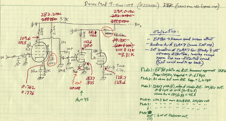
Here's the circuit at this point:
After increasing the current in the Av 12AX7, the 120K plate resistor may be too large, leaving the tube operating in a pretty non-linear part of it's curves.
1.) Above is the Differential Probe on pins 2 and 3 (grid and cathode) of the follower, 2V/div. The grid does indeed draw current during most of the positive half cycle. This is when the circuit is slightly overdriven.
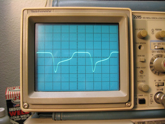
2.) This is the input signal on top of the follower out, showing flattened corner on negative half cycle of sine wave. The clipping on the positive half cycle is due to the follower drawing grid current, and the flat spot on the negative half cycle is due to the stored charge in the capacitive load addding to the input signal to the follower when the polarity changes and the follower was and is in a slewing mode of operation. The slewing is shown below.
3.) Input and 12AX7 voltage gain triode plate (rather than follower output). No sign of the flat spot on the negative half cycle (I did vary the input signal level to try and get it to show at other drive levels - it never occured), but you can see how the follower drawing grid current flattened the positive half cycle (but with nice rounded corners). The funky shape of the negative half cycle is due to how the voltage gain triode is mis-biased for the size of the plate resistor it has. Although I did this on purpose, I may have over done it. I want to be able to use this amp clean too.
4.) Input and cathode of first triode (V gain section) at 470 ohm res. No evidence of any flat spot. This is when there is a flat spot at the output of the follower.
5.) Diff. probe is across 120kohm Resistor at plate of 12AX7 V gain section. Again, no flat spot evidence here, when the follower output dies have it.
6.) Diff probe across 33kohm R feeding grid of follower, plus probe is on grid.
7.) Pins 2 and 3 (grid and cathode) of the follower again. This time it's 1Volt per div, when overdriven a bit, Plus probe on grid. Worse case in this photo is where the follower grid goes positive by 0.8 volts. When the grid of the follower goes positive relative to it's cathode, it's loading effect on the previous stage, the voltage gain 12AX7 triode, increases dramatically, very easily over powering the flimsy source impedance of that 1st 12AX7 triode. It clips the signal before it would have been clipped by the 1st triode clipping on it's own. The good part is that it's part of a desireable for guitar distortion mechanism.
8.) Diff probe across output cap that follower drives into, 2V/div. This is when the signal is high enough to cause the distortion. This cap feeds the tone control circuit (a capacitive load). This waveshape was a realativly clean sinewave at lower amplitudes, up to the point where the output of the follower started showing visable distortion.
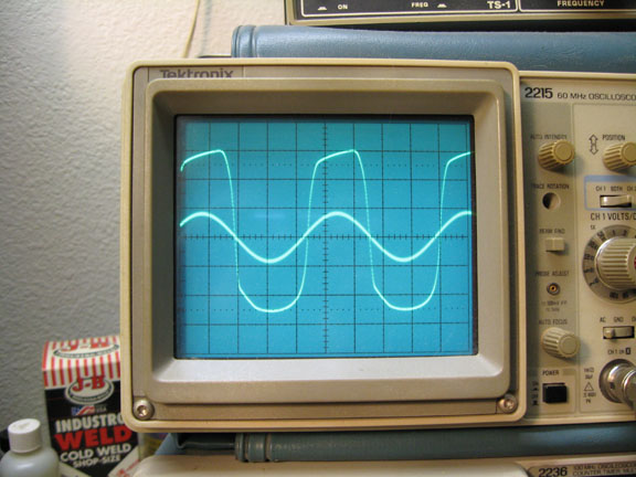
9.) Follower cathode output, 1kHZ, 20V/div.
10.) Same as above but 300 HZ. The flat spot only exists for the first half division of 300 HZ since the time constant of the flat spot mechanism doesn't change with frequency.
11.) Same as above but 4.5kHZ. Here, the flat spot eats up most of the negative half cycle.
12.) Same as 9 above, follower cathode output, 1kHZ, 20V/div., but the cap at output of the follower is disconnected from cathode. The follower is no longer driving a capacitive load, only its 100kohm resistor to ground, and the flat spot of interest on the output waveshape is gone, regardless of the input drive level. Shown here is a very high drive level.
Conclusion: The capacitance that the follower is driving is a major part of what causes the flat spot phenomenon. The clipping of the positive half cycle probably still happens even without the capacitive load (I should have shot a picture of the follower grid to cathode voltage with the cap removed - I'll go do that and update this when time allows). A 12AX7 makes a whimpy follower that slews easily when driving a slightly capacitive load - at 1 kHZ... The effect of it's reaction to being both direct coupled to the previous stage, and slewing into a capacitive load, is what gives us this arguably "desireable for guitar" distortion mechanism.
470ohm sounded as good as any (maybe better at max distortion setting) but had too little clean range, so it's back to 760 ohms on the cathode of the 1st 12AX7.
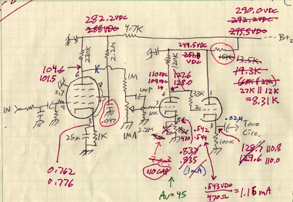
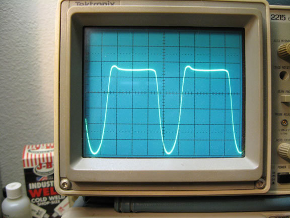
Above is 10V/div vert., viewed at output of .02uF cap. This is as high as it goes this clean.
Above is 20V/div. This is the waveshape just short of actual clipping.
Above, also 20V/div vert. The positive half cycle is now clipped (apparently from the DC follower drawing grid current).
Same as above driven a little harder. The "flatspot" is now showing on the negative half cycle.
Same as above but driven harder. The "flatspot" now dominates the negative half cycle.
This is probably a good compromise with the 10K across the 820ohm making 760ohms, but a bias switch might be the way to go, switching between 470ohms and 750 or 820. I'll live with this for a while and see if I have what I want. If I have a concern about this value, it's that the clipping happens at almost the same amplitude on both half cycles. It might sound better if there is more space between the clipping of one half cycle relative to the other.
Note: I noticed a significant difference in the clip levels between the left and right preamp channels, when viewed at the output of this follower. That could be from tube variations between the JJ EF806 pentodes or the JJ 12AX7's. Less likely from the part tolerances, but anything is possible (the cheap Alpha input Level pots?).
Next: Play through it for a while, with each guitar, both electrics and the Taylor.

Hmmm... What do you think?
Hmmm, I don't know, what do you think?
I'm not sure. What do you think?
I don't know.