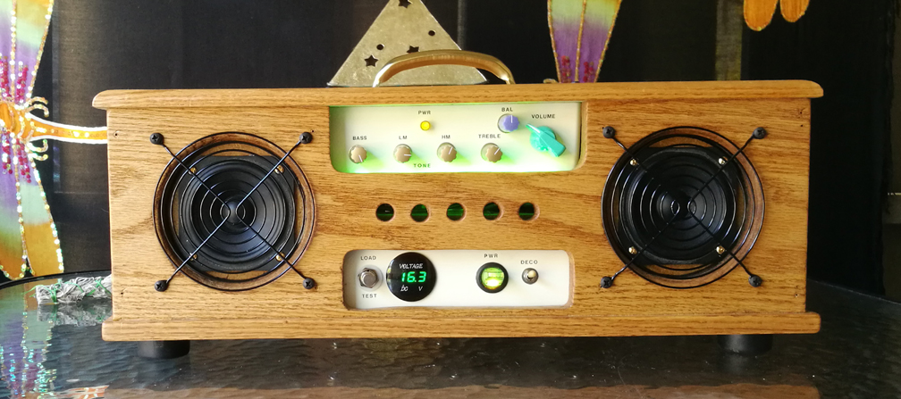

So there I was, camping in the Oregon Mountains with a beautiful amazing woman on what might be called a first date, and suddenly we wished we had some nice music to listen to. Did I, Mr. Audio Electronic Engineering Technician have a music machine? Nooooooo.
We ended up listening to music on her i-phone... Better than nothing...
It was then that I realized it's time for me to either buy some kind of boombox, or build one. I'd been planning to build one, but never got around to it.
I did a bunch of research on the web, and became convinced that all boomboxes available to buy are designed to break in about a year. Some sounded pretty good, but in the end I decided that it would be interesting to learn first hand about switch mode poweramps, Lithium and/or Lead Acid batteries, and to have a good sounding wireless boombox for any future campouts or picnics. Much like with my guitar amp projects, I couldn't find anything out there I liked enough, so I built one myself.
My first design was the size of a small guitar amp, with two 6 inch woofers and two 3 inch full range drivers in sub-enclosures, bi-amp'd with four class D poweramps, full preamp system, and a 12 Ah lead-acid battery. After getting it about half built, I decided it was too big, and the 12AH lead-acid battery was sorta heavy at about 10 lbs. When you're away from your campsite, down at the lake, you want to be able to easily toss valuables into the locked trunk of the car so they don't get stolen. I'm not the wild partier I may have been when I was young, who may have wanted loud bassy rock music playing. Now I like low level high fidelity music, more for ambience than it being the main event or fuel for a large party. So I decided to scrap that box and rethink how to do a smaller, lighter version. That's what this page is about.
I like to brainstorm my thoughts onto paper, and then think about how they could be better suited for the real world situation. There's actually a lot to consider if you want to get it right. How big and heavy do I want it to be? How would I recharge the Lithium batteries without causing an explosion? How much bass do I want to have; knowing that it's hard to get much low bass out of a speaker outdoors without significant power and cone surface area? Are the little tiny heat sinks on the poweramp boards going to be enough when sunlight could be hitting the box? Should the box be painted white to keep cooler? Should I use passive radiators to get a little more bass? How much internal volume do the speaker drivers need? How will I mount the various circuit boards, batteries, etc. Should the speaker drivers be front mounted in case they ever need to be replaced? What kind of grill cloth will I want to use for this outdoor situation, and how will that be attached? Etc. etc. etc. Here's one page of brainstorming notes:
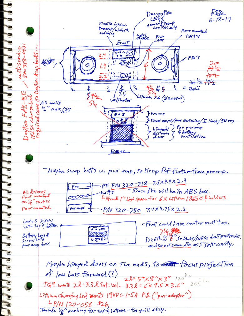
You gather information and ponder the various itterations, looking for potential problems.
Eventually, the confidence light turned green, so I drew up the following cabinet design (which isn't quite exactly what I built):
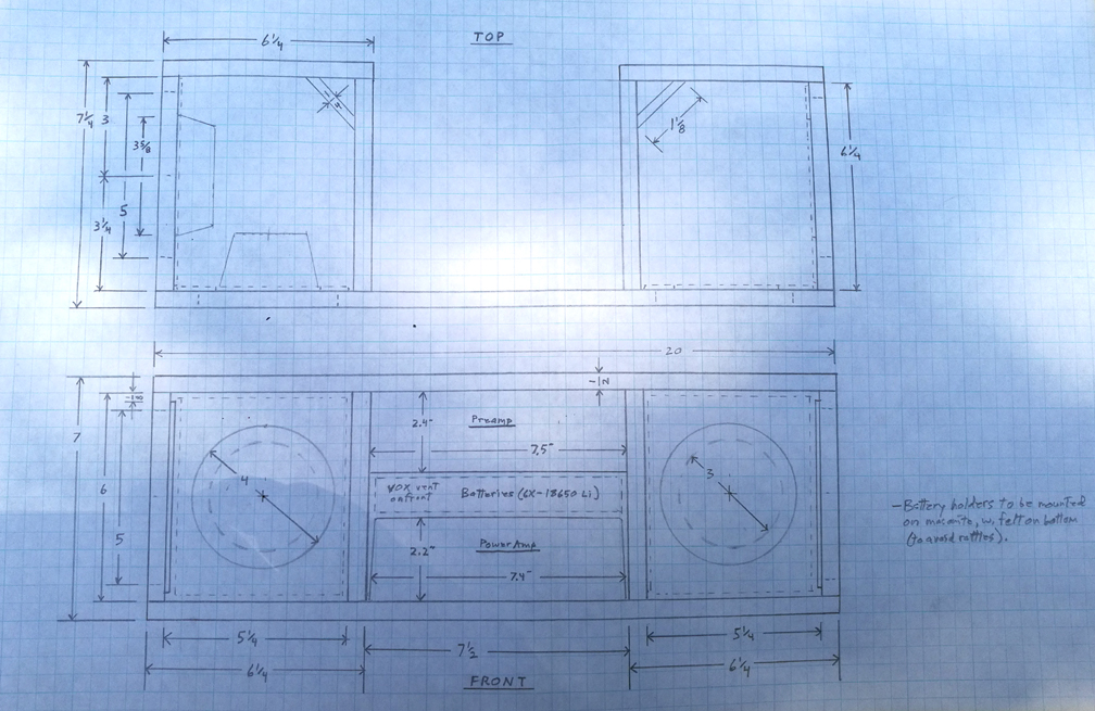
Since I wanted to wrap a grill cloth around the speaker driver areas, held on by velcro, hopefully keeping things simple, I decided to front mount the drivers on rear mounted 1/8 inch thick masonite. The rest of the cabinet is 1/2 inch red oak. That way the drivers won't protrude beyond the front surface of the oak cabinetry, and poke into the grill cloth. I later realized that fan grills are a great way to protect the speaker drivers.
I bought and tested 3 different class D (switchmode) poweramp boards from Parts Express, after reading many reviews on many different boards. Each stereo poweramp board was about $20.
2 out of 3 of the boards I bought were bad designs and oscillated. All three had many rave reviews on the Parts Express website...
Here's the test setup on my bench:
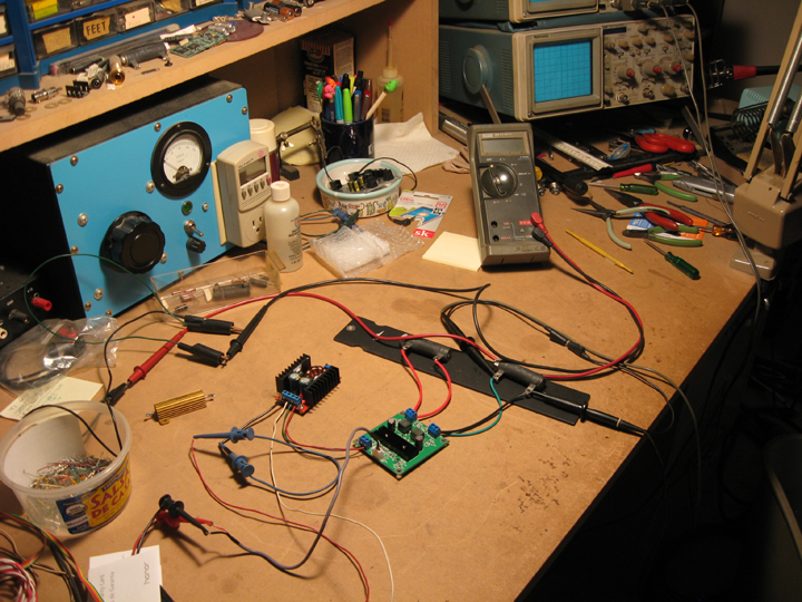
The green board shown above is the one good board of the bunch.
I was also testing a switch-mode voltage booster from Parts Express (the small red board on the left w. heatsinks), which worked pretty well. I was going to use it when I was going to use the lead-acid 12 volt battery, to get the DC up to around 20 volts, but have since decided not to.
In this version of the project, I'm just stacking in series 4 of the 18650 Lithium batteries to get a high enough voltage. The Lithiums are 3.7V nominal 2.4Ah batteries per cell (X4).
After doing a bunch of research, I still had no real idea how long the batteries would last in real world use, due to the many variables. Hence the optional external DC port, which can tap off a car, an AC adaptor, a back-up battery or whatever.
Other boombox makers are continuing to use these 18650 Lithium batteries in their projects/products, so I figure they should work good enough. They worked better than I expected.
When using an oscilloscope to view switch mode power amp output waveforms, you may well blow up the circuit if you attach a scope ground to either side of the output.
Most switchmode amps have a bridge output topology, neither side of which is ground. So you need to use a differential probe setup.
You turn on a second channel on the scope, invert it, set it to the same volts per div. as the first probe, connect the probe ground clips to each other only, and use both probes, as in the above picture.
It's nice to have a small battery around to test this probe setup with, so you can verify what your volts per division actually is on the scope screen. It can be confusing.
Also, Don't ever operate a switchmode power amp without it's outputs connected to a proper load, or it may blow up. The output reconstruction filter can generate high voltage transients when unloaded, which has been known to blow up the tiny SMD caps in that circuit.
Also, don't ever parallel voltage sources, or the one that's a slightly lower voltage will actually load the higher voltage one, causing a signficant waste of energy the whole time they are connected. Batteries are voltage sources. So are power amplifier outputs. Solar cells too.
In the case of paralleled power amp outputs, this can also cause instability, which can cause everything to blow up. Current sources can be paralleled, but not voltage sources.
Back to the amp boards:
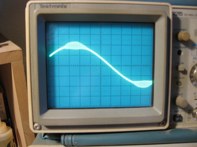
Above is the Sure brand, model AA-AB32155 which allegedly got many great reviews that are listed on the Parts Express website.
From about half amplitude all the way up to clipping, it had this ultra-sonic oscillation "bubble" riding on the 1kHZ sinewave test signal.
That would sound distorted, and may burn out the speaker and/or the poweramp itself over time. Totally unacceptable.
When pushed all the way into clipping, I got this waveform (below). Not pretty:
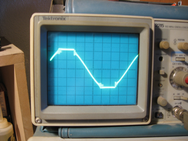
A different board which uses the TPA3116 chip oscillated at a few HZ when pushed beyond about half power (the mostly through-hole leaded-parts version of the one good board below). That's also unacceptable. Good chip, bad peripheral circuit and/or board design.
Luckily the TPA3116D (notice the D), all SMD version, worked real well. Clipping was pretty clean, and no oscillations of any kind.
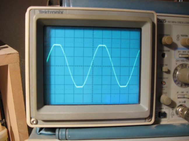
Here's the published board spec at Parts Express:
Specifications: • Power output: 50 watts x 2 into 8 ohms (24 VDC <1% THD+N) • Frequency response: 20 to 20,000 Hz • Signal to noise ratio: 102 dB (Maximum output @ THD+N <1%, A-weighted) • Power supply: 18 to 26 VDC, 2 to 6A • Dimensions: 2.7" W x 2.53 L x 0.6" H.
Greater than 90% efficiency Pre-assembled, pre-tested for superb sound quality out of the box Tried-and-true Texas Instruments Class D architecture. Anti-pop circuitry eliminates on/off popping noises
It actually works great at 12 volts, and according to the chip spec, could work well down to around 5 volts.
The thing about switch mode amps (class D, Class T, etc.) is that they have a very high switching frequency (close to 1mHZ), which means they are an Rf device, and that opens some additional cans of worms. Simple wires effectively turn into acoustic chambers (creating reflections due to characteristic impedance mismatches - the wires become "reactive"). Rf will capacitively and/or inductively couple into any high Z circuitry, and can cause significant slewing related distortions in any analog circuitry. If Rf energy is allowed to go to the speaker, it will heat up the voice coil more. These days, most music program material comes from a digital source, which may well have some Rf energy in it. So circuit board layout is very important, system wiring must take this into account, filter caps and grounding techniques will be particularly important to get right. This is why I put the preamp in a separate box.
I had already built up the analog preamp board for another project that got undone, but it's designed to work with a bi-polar power supply, so I had to create a bipolar power supply (the 2.2K R's and 1KuF caps), and tie the input and output gnd. connections to the system (pwr amp) ground for it to integrate in.
When I first hooked it all up and tested it, it had "motorboat" oscillations when preamp gain was maxed and a signal was present. This was due to the many high pass capacitors in the circuit each contributing phaseshift at the lowest frequencies.
The 9 volt LM317 regulator circuit for the preamp fixed that.
Here's the system diagram:
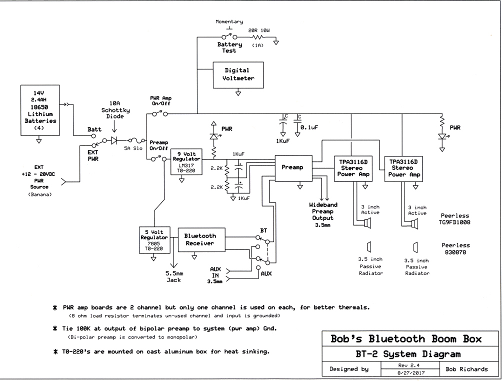
The un-used poweramp channel has an 8 ohm 3W termination resistor, and its input in shorted to ground. By using only one channel of each board, I effectively doubled the size of the heatsink (better reliability).
I chose to use Hammond cast aluminum boxes for the preamp and poweramp sections, separately, hoping that would reduce any Rf interferance problems, and not rattle due to vibrations caused by the spkrs.
My 5 year old bluetooth receiver works pretty good, but has no option for USB chip misic sources, so you potentially use up the battery on your phone after a while.
I may opt for a bluetooth receiver that also has USB and SD ports, so I don't have to use up the battery in my phone sending bluetooth.
A possibly decent one is finally available, has a remote control, and is here now waiting to be tested. Had to order it directly from Hong Kong. No duty fee.

Here's the cast aluminum amplifier boxes:
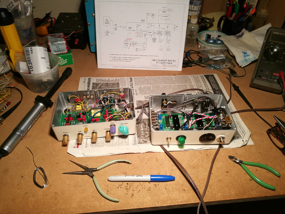
Preamp on the left, poweramps on the right. I had to have the preamp box modified such that there was no screw post in the middle of the front, in the way of the circuit board (Much thanks to Matt Kamna for that).
In the poweramp box, I added a momentary pushbutton switch that adds a 1 ampere load, and a voltmeter.
Adding a load and seeing how much the battery voltage drops, gives an indication of the internal resistance of the battery, which is a reflection of it's state of charge.
According to advice on the web (which was wrong), this battery test method works well with all battery types except Lithiums...
It turns out that the battery voltage does go down over time with use, and that is a good indication of "state of charge".
These Lithium batteries are advertised as having a 3.6V nominal output. A fully charged 18650 Lithium battery will read about 4.25 volts, and will gradually shrink down to about 3 volts with use, before I consider them needing a re-charge.
Many commercial Lithium protection circuits out there draw the line at 2.5 volts, since going below that can do permanent significant damage to the batteries, but I'm more comfortable drawing the line at 3.0V.
Charging the batteries slower (less current), and avoiding discharging them below 3volts, will help them last significantly longer.
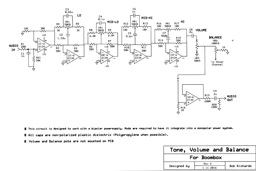
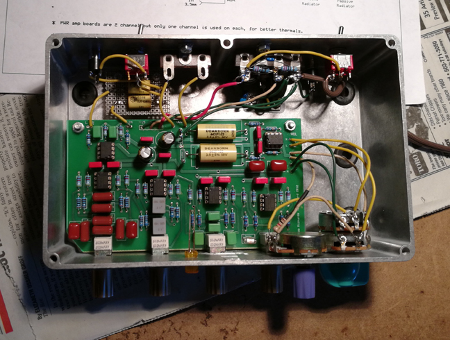
Above is the Preamp Circuit. The "Reference Designator" numbers are not updated, but all part values are right. I used the OPA2134 dual opamp chips. TL072 chips would work fine too.
This circuit is my own design based on what I've learned over the decades. I don't know of another preamp I'd rather have.
This circuit allows you to create a real good reverse Fletcher-Munson ("Loudness Compensation") curve, besides general tone adjustment.
Now for the cabinet:
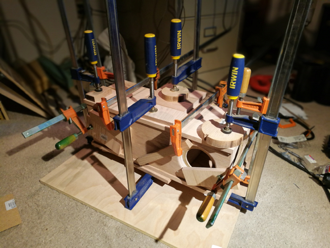
And here's the cabinet being built. All 1/2 inch red oak, except for the masonite speaker subpanels and the battery board.
Oak is a bit heavy, but very durable, and holds nails and screws very well.
The only reason I used nails was to keep everything in alignment when the clamps are tightened after the Elmers outsoor carpenters glue was applied. After the glue had at least 24 hours of drying time, I removed most of the nails.
The top stays off until everything else is verified done and in.
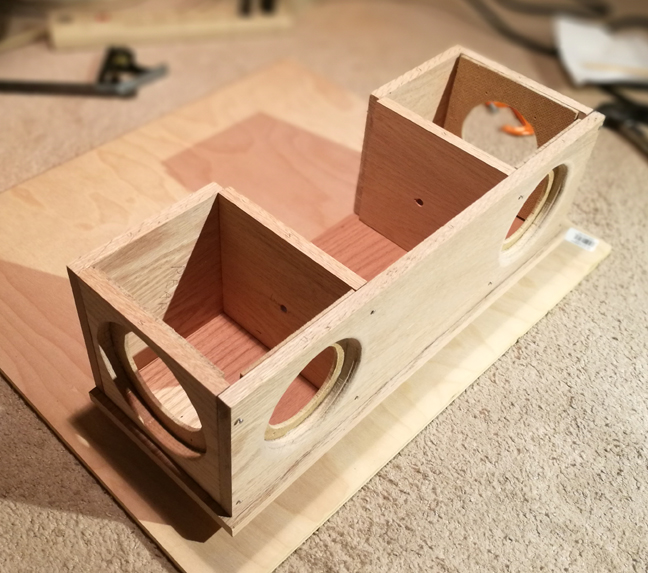
This is the part where you go, "Ooops, I forgot to cutout the front board holes for the front facing control panels..."
But with a little ingenuity I got that done. The holes for the speaker wires need to be drilled before assembly, unless you have one of those right angle drills.
Here it is a week later, with front panel cutouts and wood stain on. The row of 1/2 inch holes are for ventilation. The Lithium batteries will be right behind them.
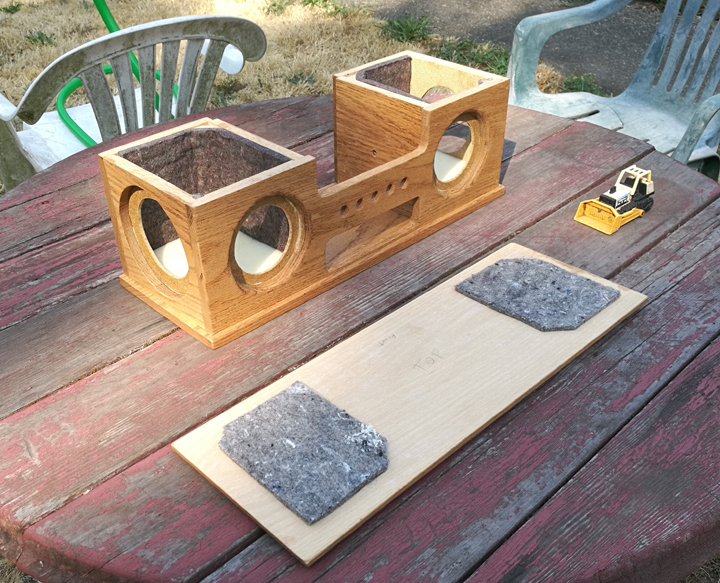
Front view above, rear view below.
The top and bottom have a "lip" (extend beyond), so the speaker grills will be less likely to get damaged by real world issues.
After gluing in the acoustic padding with Liquid Nails, a very toxic-fume glue, I prefer to allow it at least a few days to dry and air out, before mounting speaker drivers and closing things up.
Acoustic padding is more effective when glued tight to internal surfaces, not just thrown in loosely.
MDF (fiberboard) turns into a "wet cracker" if it gets a lot of moisture, so should only be used for cabinets that will be in a climate controlled home. Oak is much more practical for outdoor use.
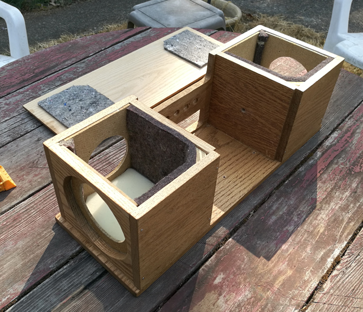
Below is a closer look at the acoustic insulation I'm using. 3/8 inch thick Wool felt (car upholstery padding) on every surface, and an additional piece of 1/2 inch thick foam rubber on the bottom.
Resonance in an almost cube shaped enclosure would be pretty bad without the acoustic absorbtion materials.
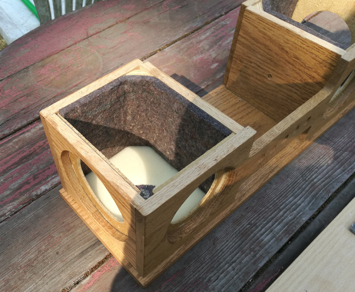
I also added a significant wad of "acousta-stuff" (not shown) (similar to fiberglass) before sealing the cabinet.
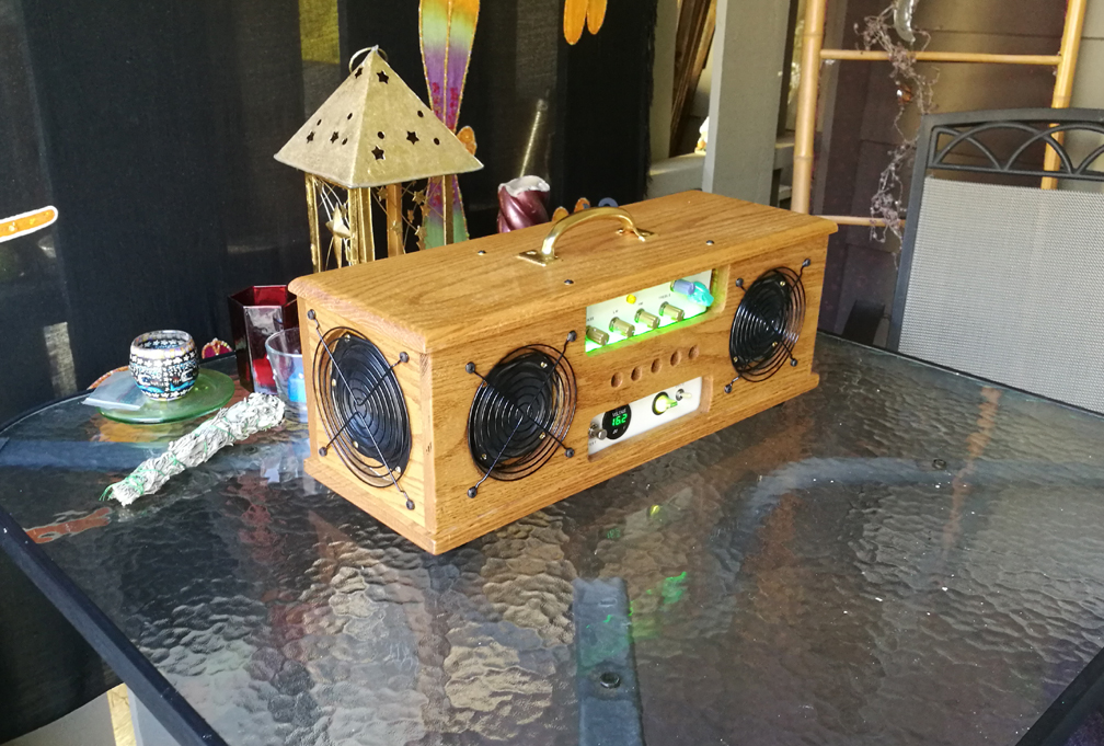
Here it is finished:

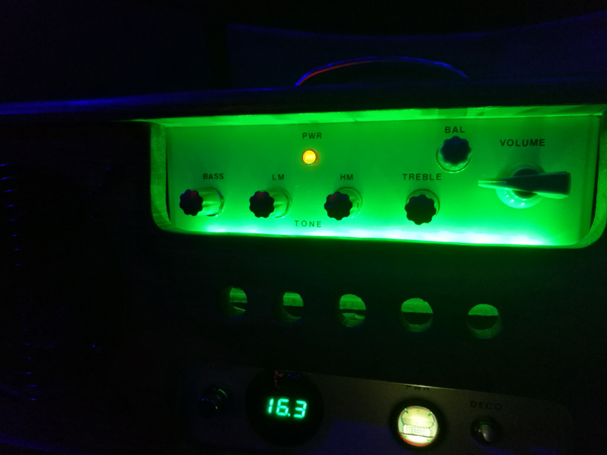
The switch on the poweramp box labeled "Deco" is for the row of green LEDs that shine up on the preamp control panel. At night in the dark this is very nice.
The 1 ampere Load Test switch isn't necessary. I thought it might be when I believed much of what I read on the web about Lithium batteries.
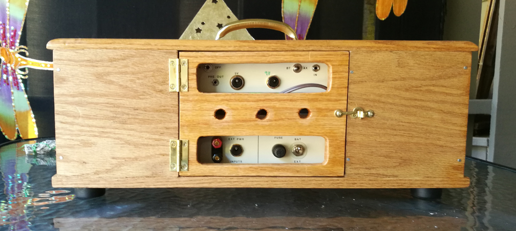
The rear door opens for battery access or for servicing the electronics.
These class D poweramp boards have virtually no turn-on or turn-off transient (very nice), but the preamp generates a bit of that, so I put a preamp power switch on the back of the preamp box, so I could turn that on before turning on the poweramp, to avoid the transient (click sound).
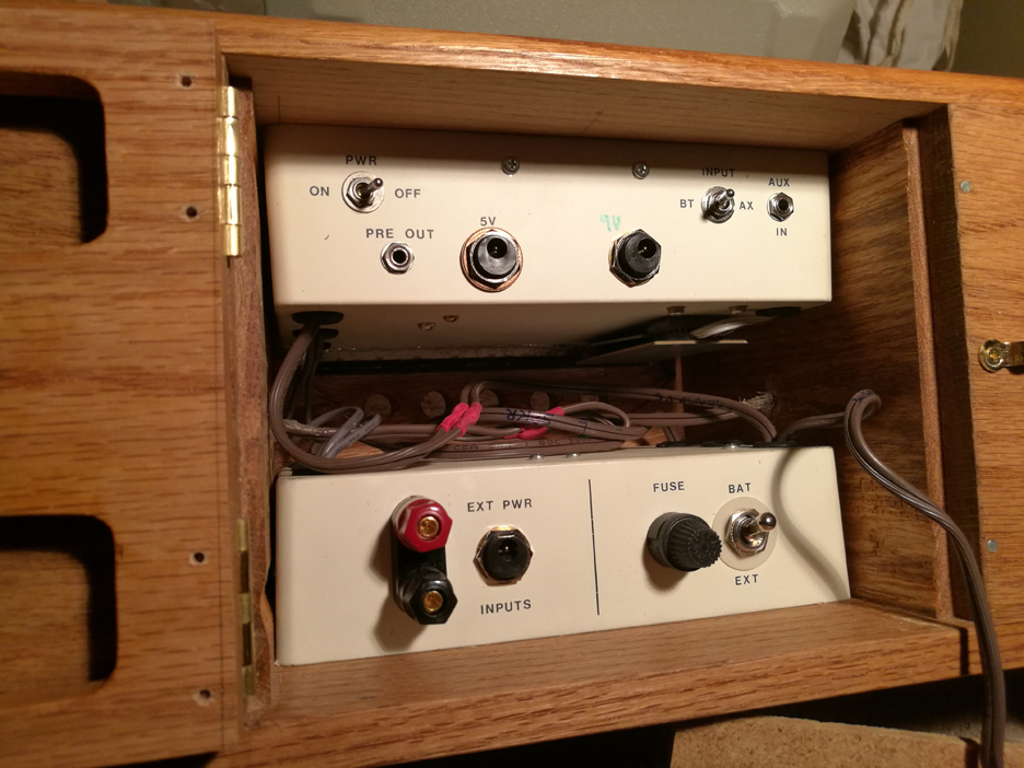
Above you can see the Bluetooth receiver board velcroed to the bottom of the preamp box. The brown wires are for speaker and power supply hookups. Preamp outputs feed poweramps thru shielded cables (gray).
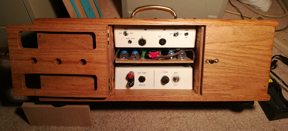
The battery board has a fairly tight fit due to all the cables, but that's why it doesn't rattle, so it's a good thing.
Since current draw can be several amperes, I used banana style connectors rather than those little conventional ones that have much less contact area.
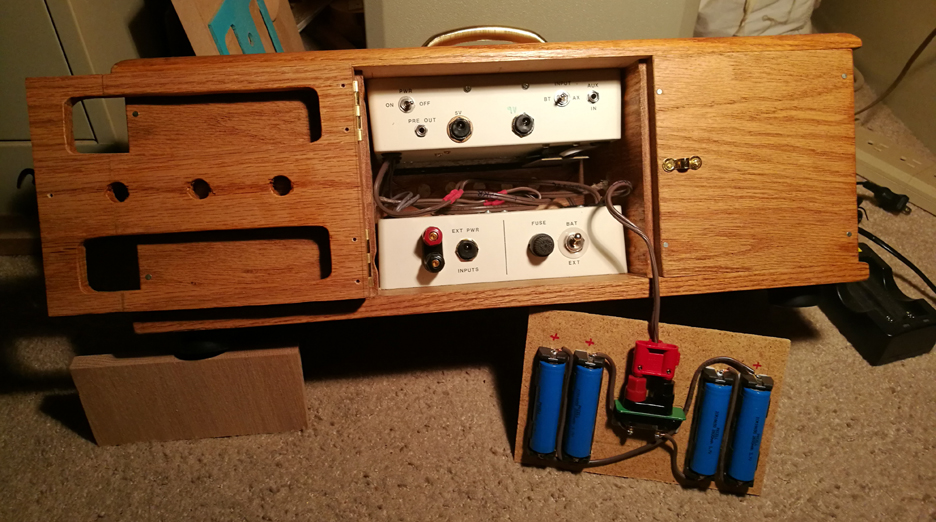
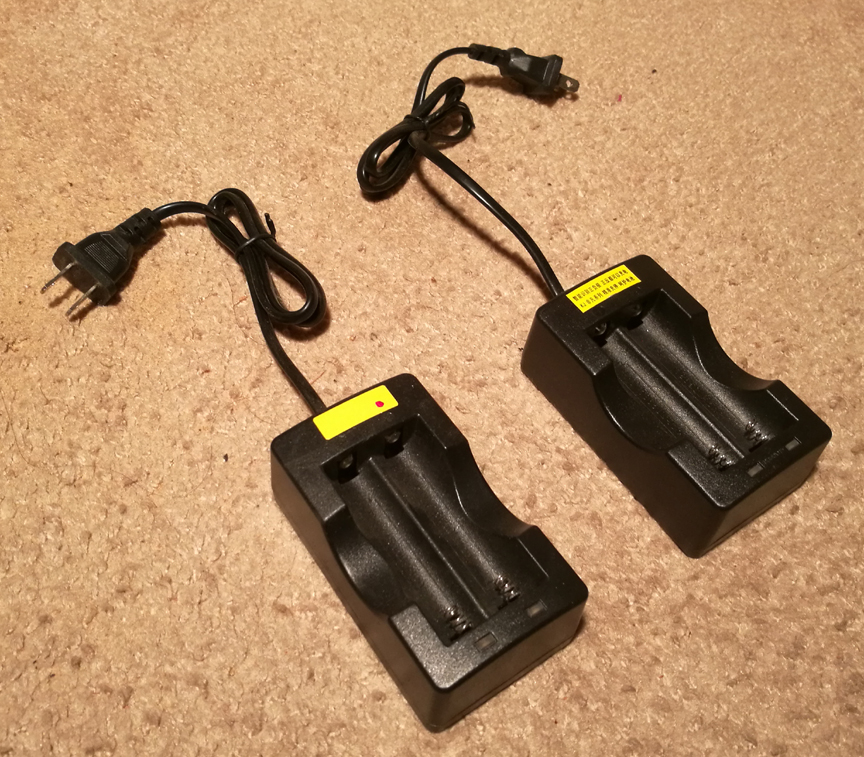
Below are two "brand X" (Chinese) Lithium-ion battery chargers, bought from Amazon that seem to work fine.
These TC9FD1008 $12 speaker drivers are low efficiency at about 85dB 1w1m, but they have a relatively flat frequency response and decent Xmax spec for their size.
They do a pretty amazing job of putting out 50HZ to about 15kHZ. The passive radiators and tone control circuit EQ pump up the low bass significanty.
When the unit is placed on a table against a wall, the bass gets significantly better reinforcement. The 4 Baxandall tone controls allow you to get a very pleasant, easy to listen to sound.
The batteries lasted much longer than I expected. I used it for two parties with the ladies up the street (several hours each), and they still had significant charge left (measured about 3.5 volts per cell - down from 4.2VDC). Volume was usually low/normal, occasionally maxxed for certain songs.
If you want a really loud boombox, I'd highly recommend bi-amping, and as large a woofer as you can stand to have/carry. This goes loud enough for me, has relatively high fidelity, and is small and light.
Below is a better shot of the passive radiator. It's slightly larger than the active speaker drivers on the front, and required the next size up in fan grills. I didn't mess with the tuning weight on the passive radiator. It seems to work great as it came.
I used an internal cabinet volume that would be appropriate for the active TC9 driver with no passive radiator, based on a software I have (WinISD beta). That approach worked good in the past.
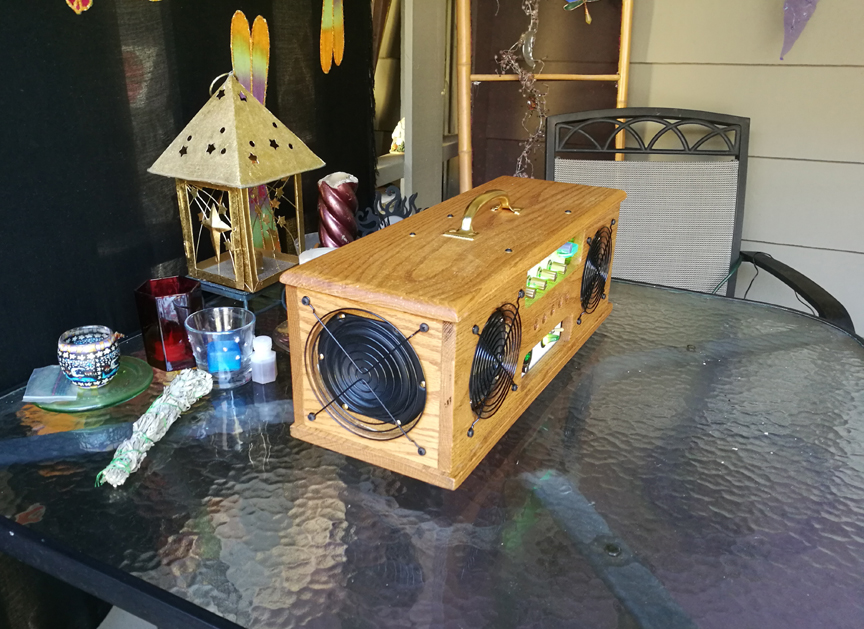
There's no battery charger built in. I really didn't want the box to get bigger.
Here it is in the dark with the Deco lights (LEDs) on. The "16.3" is the battery voltage. When it gets down to 12.0, it's wise to turn the unit off until the batteries have been recharged.
When I tested the class D poweramp boards on my bench, the tiny heat sinks never got hot, although the 20watt load resistors got so hot they melted some wire clips that were attached to them.
Since this Boombox will get used on campouts in the mountains, possibly with direct sun shining on it for hours, I wanted to avoid pushing the poweramps to their limits (for better reliability).
I did this by using a lower power supply voltage (they can go up to 24VDC), using only one channel of each stereo class D amp board per speaker, using 8 ohm speakers and having the ventillation holes on the front and the back of the cabinet.
I didn't want to ventilate the metal boxes because I didn't want bugs to ever get in there.
Both metal boxes are recessed about 1/8 inch behind their front cabinet hole cutouts, for additional ventillation. I almost painted the cabinet white, for better thermals in the sun, but the oak looks too nice.
