The Behringer products look very good on paper (specs), especially for the dollar amounts, however... Behringer doesn't seem to be very good at analog circuit engineering. Although I couldn't find a schematic for the exact unit I have (the DEQ2496), I've seen schematics for very similar Behringer units such as the one Gary Pimm has (the DCX2496), which shows several pretty bad design flaws.
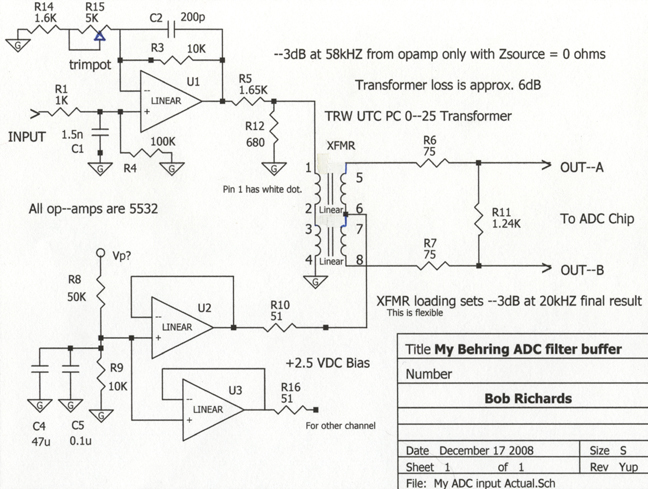
Behringer's DCX2496 Input circuit feeding the analog to digital converter chip:

A close look at the components on the circuit boards in my unit showed that there was a difference in part values, but not likely to the point of it being significantly better. It appears that Behringer is primarily concerned with conventional specs on paper, as opposed to quality and fidelity in the real world. More specifically, they have an unbiased electrolytic in the front end causing distortion, most opamps are running into ridiculously low Z loads (mid-hundred ohms) thereby generating substantial distortion and compression at higher signal levels, the differential receiver at the output of the DAC is the cheap-ass psuedo-balanced topology, and in my personal opinion both the anti-aliasing and reconstruction filter corners were set too high.
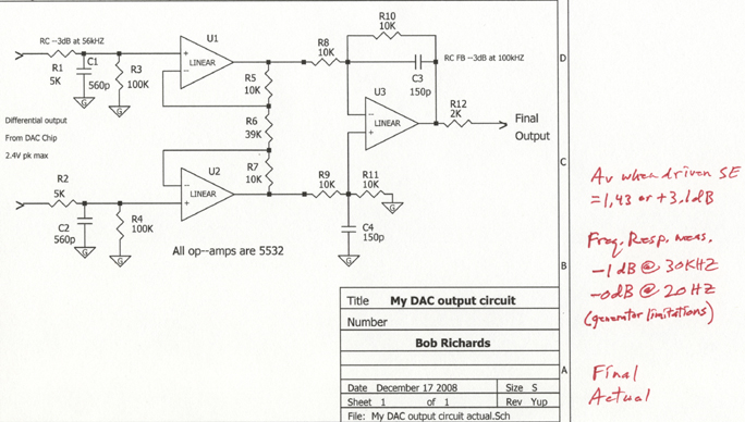
Behringer's DCX2496 output circuit receiving a differential signal from the digital to analog converter chip:

Behringer DEQ 2496 Before mod:
Like Gary Pimm, I "just said no" to both the input buffer/filter circuit feeding the ADC chip, and the DAC output reconstruction filter circuit. To feed an ADC (analog to digital convertor) chip properly, you want to have the proper gain so it never clips, but also you want to be using most of its dynamic range or you get low-bit digital distortions, and you need to have an adequate anti-aliasing low-pass filter. Without an anti-aliasing filter, you run the risk of generating some "foldover" distortions that will have nothing what so ever to do with the frequency you sent in the input. With the high clock rates in this unit, I'm probably more conservative than I need to be (-3dB at 20kHZ), but with digital it's hard to be sure what is really going on. Documentation is often misleading in its attempt to sell you something.
When I became convinced that I needed to redo the whole analog section of my unit, I first needed to know what signal levels I was actually feeding to the Behringer unit in my particular system, which is a Carver preamp signal processor loop. I hooked my oscilloscope up to the place where the behringer would be, and played many CD's on my $150 Panasonic cheap-ass DVD changer. I was surprised at how much the signal levels on various CD's varied. Here's the test results:
The highest peaks appeared to be:
| FM tuner selected rather than DVD/CD player | 1.5Vpk |
| Eric Clapton CD | 3.2Vpk |
| Santana CD | 3.0Vpk |
| Elton John CD | 2.5Vpk |
| Jam with Chuck and friends (my own recording) CD | 3.3Vpk |
| Titanic movie soundtrack CD | 2Vpk |
| Beach Boys CD | 3Vpk |
| Magical Mystery Tour CD | 2Vpk |
| Afro Celt Sound System CD | 3.5Vpk |
| Sarah MacLachlan CD | 3.5Vpk |
| Fiona Apple doing Across the Universe CD | 3.5Vpk |
| Enya CD | 3.5Vpk |
| Clapton on Stevie Ray Vauhn tribute CD | 3.5Vpk |
| Axel F song | 2Vpk |
I listed this whole thing to show that I did take a wide range of samples, and they do vary substantially. You almost want to put an auto-volume control ahead of the ADC, just to avoid low-bit usage distortions on lower level CD's. Anyway, I set my clip point at 4Vpk so I'd virtually always avoid any clipping, but also use most of the bits in my digital processor.
As far as the anti-aliasing filter in the ADC circuit, the advertised sample rate appears to be 96kHZ. The way it works is that if you apply an input signal with a frequency higher than half that (48kHZ), the signal at the output will "fold over" thereby creating aliasing distortion. If you apply 49kHZ, you will in theory get 47kHZ out. If you apply energy at 50kHZ, you'll get 46kHZ at the output, and so on. Not my favorite distortion. So you want to have the input signal rolled off by the time you get to 48kHZ to the point where the aliasing distortions will be at least 50-60dB down. Good luck. In reality, I've been told that digital processor chips have figured out how to effectively get around this. I don't know enough to know how true this is or how it's actually done, but it must be true to a big extent. Some kind of digital filtering within the ADC chip. Anyway, being one who's hesitant to trust anything anyone ever says, I set my front end low pass anti-aliasing filter to roll off 3dB at 20kHZ. It may only be down about 10 dB at 48kHZ, so I'll still be relying on that digital anti-aliasing filter inside the ADC chip. I can easily pump 20kHZ back up with the 31 band graphic EQ, or the parametric EQ functions. This unit also has fully adjustable compression, limiting, stereo imaging, delay, and maybe something else. It does a lot if you want it to.
Below is the front end ADC chip driver circuit. The chip requires a 2.5VDC bias on each input, and the DAC chip output signal will also have a 2.5VDC bias level that the AC signal rides on.

The ADC chip has differential inputs, and the DAC chip has differential outputs. You don't have to drive or receive differentially, but it's better to (lower noise and possibly better linearity). I opted to use transformers to phase split in the ADC drive circuit, since they provide a convenient way to apply the necessary 2.5VDC bias, and because Matt gave them to me for free with encouragement. I tested them myself on my bench to see what kind of freq. response they have. They're real good when loaded as per spec. I mis-loaded them on purpose to get the slight rolloff characteristic I wanted (-3dB at 20kHZ). It's the dominant pole in my anti-aliasing filter function.
I can't believe I'm actually doing this whole mod thing, rather than throwing the dam thing in the trash like any normal person would have done... I guess I like to use the knowledge I've gathered over the years, I don't believe in throw away products, and you always learn something new in most projects. Behringer appears to have done a real nice job in the digital section.
Time to get building.
I used the SPICE circuit analysis program to verify my filter designs before actually building them up. I yanked the entire I/O board out of the Behringer and shelved it in case I needed to look at it later. Not having any schematics, I was guessing/hoping that I would get away with that. The digital circuits may have needed to see something else on that board in order for the unit as a whole to work properly. It seems that I got away with the yankage. I had the idea of bolting a small Bud brand cast aluminum box that I just happened to have laying around, to the back of the chassis, and house my circ. inside that box, away from any digital noise from the proc board or power supply. That way I could still stack the Behringer between other components on my stereo shelf, and the circuit would be well shielded.
DAC differential receiver and reconstruction filter function.

Above is the DAC output buffer, and reconstruction filtering. Using a true differential receiver topology, both DAC outputs are received with the same impedance and gain, as opposed to the half-ass way Behringer did it where neither is true. The output signal of any DAC is made up of tiny stair steps rather than smooth analog waveforms. To avoid sending high-spectra (supersonic) energy into any down stream items that aren't optimized to handle that (such as high feedback amplifiers or tweeters), it's always nice to have a low-pass filter of some kind in there. Since my sinewave generator only goes up to 30kHZ, I couldn't actually verify the -3dB point, but it's somewhere around 50kHZ according to the SPICE program.
I set the total gain, input to output to 0.85 or -1.41dB with the EQ setting at flat. Now the volume control on my preamp won't be as hyperactive. The total frequency response measures flat to 15HZ (waveform showed distortion below 12HZ, maybe the transformers or maybe my generator AGC fucking up), and -3dB at 19.3kHZ. Again, this little bit of rolloff is easily compensated for with the EQ settings. My VCC measured +14.69VDC, -15.12VDC (typical of 7800 series regulators), and the bias measured 2.42VDC (thrown off a little by the 7800 regulators).
I used all 5532 opamps rather than the newer trendy Burr-Brown OPA2134 that Linkwitz and many others are using these days. The BurrBrown should be better, but when I was using one a while back, I observed it slewing badly while driving an interconnect cable at about 50kHZ with something like a 100 ohm series R on its output. I wasn't impressed. I didn't do the same test with the 5532, but I've always had good luck with them, they always sounded real good, and they are designed to drive heavier loads than many conventional opamps, and I've got a bunch of them.
There it is, all done.

I should have been a jeweler or a neurosurgeon.
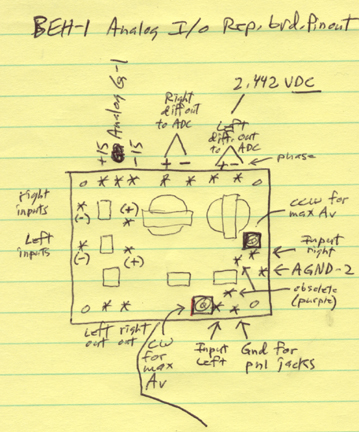
I brought out the +/- 15 VDC from the power supply (7800 series regulators) to use for the opamps, with additional polyprop cap filtering (several uF - very important - I have several uF near the board and 1uF right on the board). I soldered wire-wrap wires to pads on the multi-layer behringer digital board just out from the ADC and DAC chips, and had to remove a few parts (caps) from that area (across inputs which would cause substantial supersonic peaking of the freq. resp. in the transformers). Apparently all other analog I/O parts of any significance were on the rear panel Behringer I/O board, that I apparently don't need any more (you do lose the cal'd mic input though, if that matters, when you dump the rear panel board - I may be able to add that back in later). I brought the ADC and DAC connections out to a physical buffer board (terminal strip doo-dad) so those tiny wires would have minimal further jostling. I should have glued them in place with silicone rubber cement too.
The transformers were just a smidge too tall for the cover of the bud box to fit on tight, so I stuck two little washers around each of the four screws so the screws could be tight, but the lid of the box has a tiny gap (see below).
Aren't you done with that thing yet?

Test results:
Above is the output of the ADC driving circuit. I designed it so the op-amp clips just beyond where the ADC chip gets over driven, so as to minimize the chance of damaging the ADC chip, which clips at 2.45 volts pk. The above photo shows that the opamp clips when the signal reaching the ADC chip is at 3Vpk.
Above is a final test of the analog in through the analog out, everything included. With five volts applied (1kHZ sine) you can see the clipped output. The blurring is because of camera movement. That's what digital clipping looks like in this unit.
Above you can see the clean output (lower trace) when a 4Vpk signal is applied to the input. The trimpots on my board allow me to set this, depending on what system I want to use the unit in. In my system as it is right now, this number seemed best.
This is what us laid off electronic engineering techs do I guess... I was a hobbyist first, and probably forever. I hope this is of help to anyone out there. It was a lot of work that I shouldn't have had to do, but what the heck. Now it's a pretty nice unit to have. Sure would be nice if Behringer would cough up a schematic. I think they're too embarrassed. The Behringer service reps I talked with over the phone (more than one) said the support they get from the company is crap, and they don't recommend any of the Behringer products. Apparently Behringer considers all their products not cost effective to repair (designed that way?). If a product breaks within the warranty period, the service rep. said they just give you a new one, and throw the old one into landfill... Oh well. One pleasant surprise was that the built in Input Level indicator LED's turn out to be perfectly calibrated. At clipping, the red LED just comes on. Perhaps driven by the ADC chip itself.
A week later: It turns out I was wrong to think I could see the actual peaks of program material on my oscilloscope. The 4 volt input clip level is perfect for the DirecTV tuner and the Carver FM tuner, but CD's on my $150 Panasonic DVD changer were causing the red light to go on pretty regularly. I decided to fix the problem by puting a 6dB attenuator in the cable going from the DVD player to the Carver preamp. I put 24K ohms in series and 50Kohms to ground for the attenuator. The 50K resistor will parallel the 50Kohms input impedance of the preamp input for an effective 25Kohms. The DVD changer will still see 50Kohms as the load, and the preamp input doesn't really care what it sees, which is about 12Kohms source impedance. 6dB was a guess which turns out to be about perfect. The input level LED's show optimal use of the dynamic range, and when you switch to video the level is about the same. I haven't seen the red LED (clip indicator) flash at all since.
It sounds very excellent.

What will I do next... a center channel circuit, to improve the holographic generator mode?
![]()