The Aurium Waveguide
Open Baffle Speaker System
(c) copyright, Robert B. Richards, 2014
The Aurium Waveguide speaker system is a tri-amp'd open-baffle
(mostly dipole) speaker system, with an active 4 pole Linkwitz-Riley crossover,
which has active woofer EQ and open-bafle EQ. It's a satalite/subwoofer arrangement,
so the woofers can be positioned independently from the satalite speakers for
better interaction with room acoustics . I've also included my variation of
the Bob Carver "Holographic Generator" in the crossover chassis (bypassable).
The two sealed woofer cabinets are "monopole". The
tweeter is monopole from 1.4kHZ up to about 7kHZ (The 7kHZ can be easily modified).
It's my opinion that between roughly 1kHZ and 6kHZ monopolar is likely to give
you better stereo imaging effect clarity than dipole, since fewer inconsistent
room reflections will cause less balance deviation in the critical imaging frequency
range. From 100HZ to 1.4kHZ, and from 7kHZ - 25kHZ this speaker system is dipole.
Inter-aural crosstalk, which exists in virtually all playback
systems that use speakers, significantly damages imaging cues below about 1kHZ.
This is because inter-aural crosstalk needs to happen only once, or our ear-brain
mechanism won't know how to interpret it. In a true stereo recording, this will
happen at the recording end. If it happens again at the playback end, our ear-brain
mechanism gets confused, and imaging isn't at all what it could be. So it's
the frequecy range of about 800HZ - 7kHZ where the majority of the stereo imaging
magic happens.
There are two ways to minimize this issue (that I know of) in
a typical playback system. One is to use an inter-aural cancellation function
(Carver or Polk methods), which require the listener to sit exactly centered
between the L and R speakers and back a certain distance, forming some variation
of a triangle with the speakers. (and have little or no side wall reflection
issues). Another approach is to have speakers that are "open-baffle"
below about 1kHZ, to reintroduce an arguably false sense of depth in the frequency
range below 1kHZ, where we sense image location by timing or phase differentials,
rather than amplitude differentials. This "false" sense of depth synthesis
works fairly well in many rooms, as opposed to the Carver or Polk interaural
cancellation methods. For the person who's willing to sit in just the right
place, I've developed an inter-aural cancellation circuit similar to the Carver
one, that can be engaged, for that extra sense of being there with the musicians.
These two methods of bringing back a sense of being there in the lower midrange
frequencies can actually work well together, rather than getting in each others
way.
Above about 6kHZ we sense image location differently due to the
size of the wagelenths. The shape of our outer ear comes into play and helps
us sense height as well. It's my opinion that high treble, above 7 - 12 kHZ
sounds significantly more "real" when it's emitted out both the front
and rear of a speaker, especially if the rear tweeter can be angled upward,
so the highest frequencies come from above as well. Comb filter effects from
having two tweeters is a non-issue because of the path length differential being
so much larger than the wavelengths involved. The combfilter cancellations will
be too close together for us to perceive them. This adds "air" to
the cymbals, and doesn't really damage anything, unless the wall behind the
speakers is absorbtive on one side and reflective on the other, in which case
the rear tweeters can be disabled.
The rear tweeter has it's own Banana jacks for the highpass capacitor
and/or resistor, so it's fully adjustable in both cut-off frequency and amplitude,
depending on what works best in a given room. Like all of my speaker systems,
this one is experimental to some degree. I always like to throw in something
different, that might flop, that I can learn from. In this case it's mostly
the vertical line array of 100HZ - 1.4kHZ five inch drivers, which in theory
could work better with floor to ceiling reflection issues. This lower mid range
wave propogation will be significantly more directional on the vertical axis.
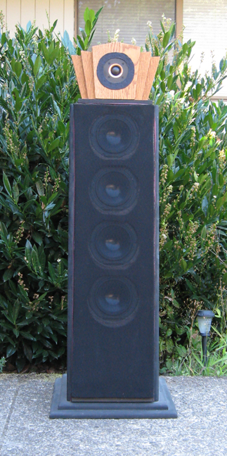
Front View
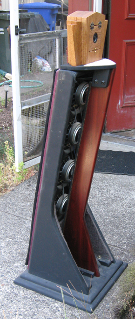
Rear Side View
The Tweeter Tower shelf never quite touches the front baffle
board.
The tweeter tower has its own mechanical "return to ground".
This way, the tweeter output will avoid the vibrational modulation,
caused by the 5 inch drivers. Probably a non issue.
The real reason for the waveguide fin on the back side is to
help diffuse the rear waves a bit, so hot-spots would be minimized.
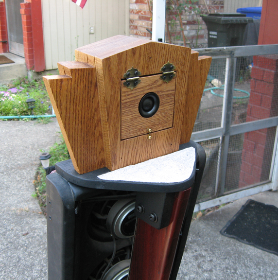
Rear Tweeter
Snell had a similar rear firing tweeter on their top of the
line system in the mid 1980's.
They were in one of the listening rooms at Dolby when I worked
there back then.
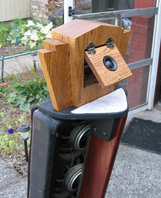
Rear Tweeter Angled Upward
The rear tweeter is a 3/4 inch Dayton dome with a neodymium
magnet.
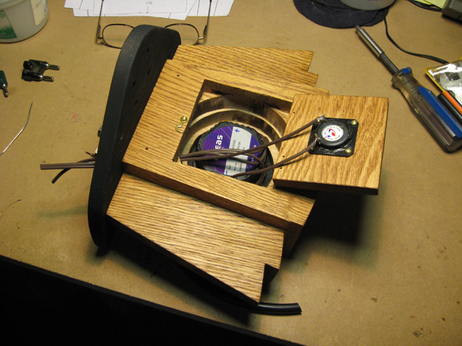
Tweeters Being Wired
I'm not convinced that it makes any significant difference,
but I wired the rear tweeter to be "di-pole" (out of phase with the
front tweeter) rather than "bi-pole"
The more important thing is to be consistent between the two
speaker systems.
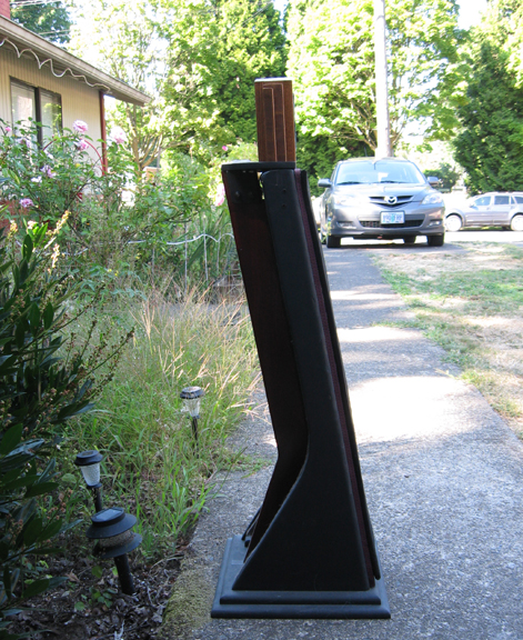
Side View
The front of the baffle board has two layers of 1/4 inch thick
acoustic padding (like felt), to minimize any emission from panel vibration.
One layer is glued to the baffle, and the other with grill
cloth attached to it, is held on with velcro.
The 10 degree tilt reduces floor bounce comb filter effects,
and reduces time alignment issues with the four 5 inch drivers.
Any vertical line array of any length will have less of a floor
and ceiling bounce comb filter issue. The longer the better.
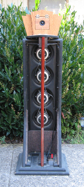
Rear View
I put acoustic dampening material in the lower rear area to
minimize any cavity effect on the rear emission. All bracing is Oak.
The vertical triangular oak braces at the sides of the back
of the baffle, minimize acoustic impedance and cavity effect issues, and further
brace the baffle board.
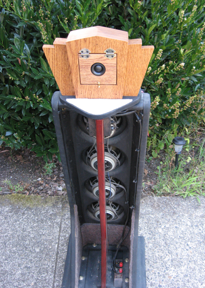
Looking South
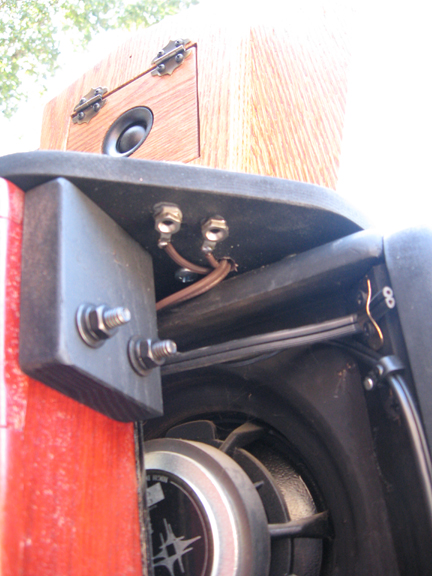
Banana Jacks Epoxied into the underside of the Oak Shelf for
the Rear Tweeter allow fine tuning for a given room situation.
That line cord wire that goes horizontal in the above picture,
is the stabilizer mechanism for the tweeter tower.
It attaches to the baffle board at the sides, and to the tower-stand/waveguide-fin
in the middle.
Keeps it in place over time horizontally, but dampens out virtually
all vibration on the Z axis.
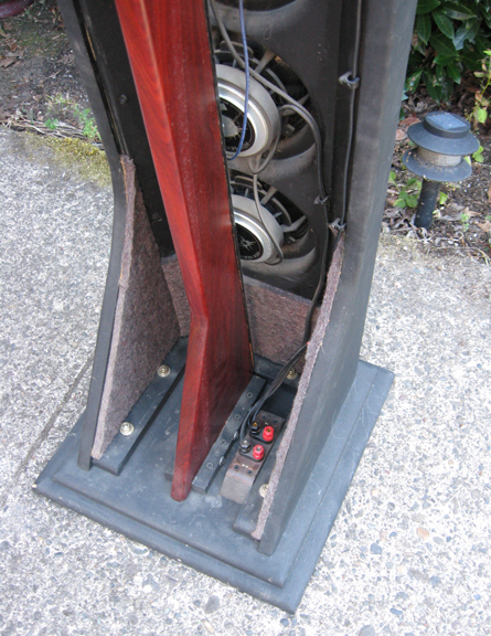
Electrical Interface
The Building Process
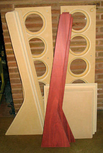
Most of the big pieces
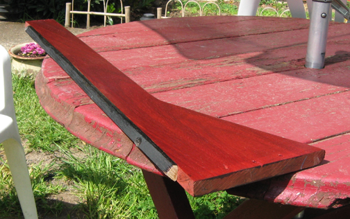
The reddish wood is called Bloodwood or Satine. It's harder
and heavier than oak. Apparently a bit rare.
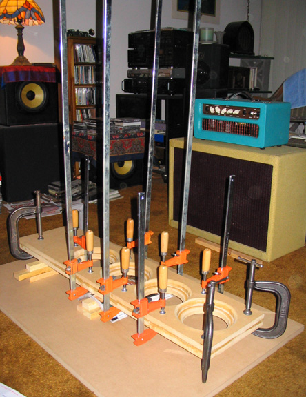
Making the Baffle Board
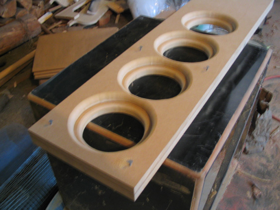
I routered the back side of the driver holes (1/2 inch radius)
to minimize acoustic impedance effects. The drivers were mounted with wood screws
and silicone rubber glue.
After the lamination glue dried (1.5 inch total thickness),
I ran it through the table saw again so the sides of the front would be absolutely
flush, and bond fully to the side panels below.
I consider this to be particularly important.
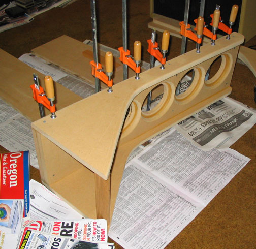
Attaching the Sides
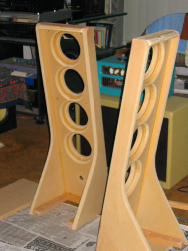
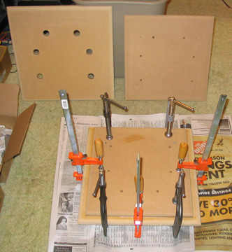
Making the Bases
Six big bolts attach the bases to the baffle.
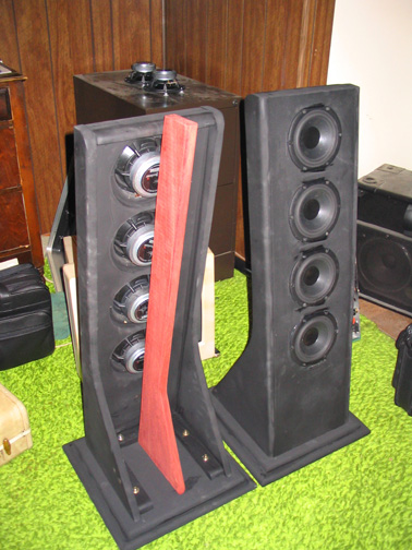
Checking the waveguide/tweeter stand for any issues before
bolting it in.
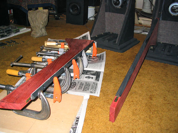
Creating the waveguide finn.
The triangle brace is there to minimize acoustic impedance
issues.
The Woofers (2)
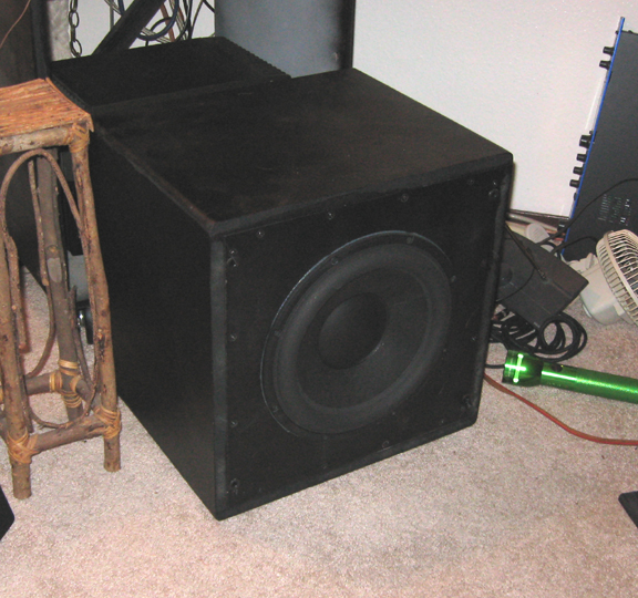
Peerless XXLS 12 inch driver in a sealed box, driven with active
EQ making them acoustically flat down to 20HZ (with a fast drop off below that).
The Mid and Tweeter Drivers
I researched a lot of drivers and ultimately went with the
same drivers that were good enough for Sigfried Linkwitz, who's technical expertise
I have a lot of respect for.
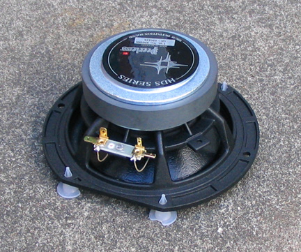
The Midrange Drivers
Same as in the Original Linkwitz Pluto system.
The special 3 layer cone (whatever that's supposed to mean)
is hard enough to have a small break-up peak of a few dB in the frequency response
at around 5kHZ,
but the 4 pole crossover cuts them off at 1.4kHZ, so it's a
non-issue.
Any time you use hard cone drivers (Kevlar, metal, ceramic,
etc) for woofers or midrange, you should get better clarity ("resolution"),
but those drivers all seem to have a severe resonant peak in the upper midrange
(3-6kHZ), right where the ear is very sensitive. That would be very hard to
listen to over time.
Hard diaphram drivers usually necessitate the use of crossover
networks that have very steep rolloff rates (such as 24dB/octave),
so this horrible resonance will be rolled WAY off.
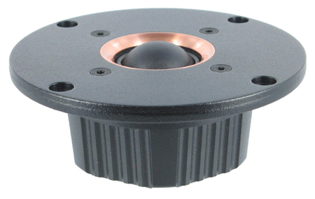
The Front Tweeters are Seas Millenium 1 inch Domes.
Same as is used in the Linkwitz Orion system.
There were not many 1 inch dome tweeters that could be used
all the way down to 1.4kHZ
and not have I.M. distortion or frequency response issues,
even with the 4th order rolloff.
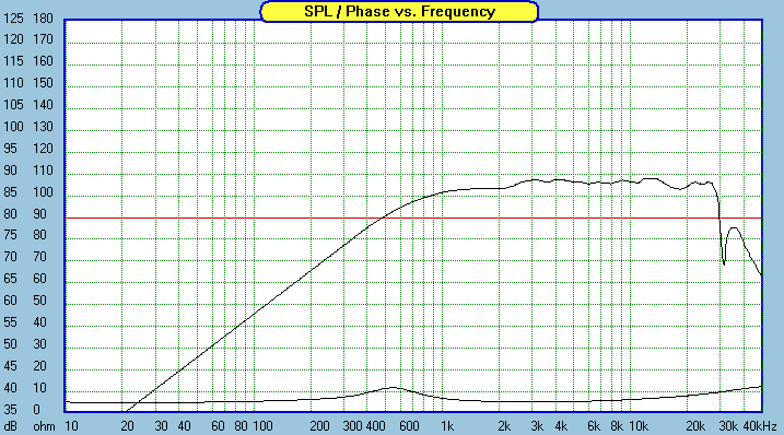
Frequency Response from Zaphaudio website
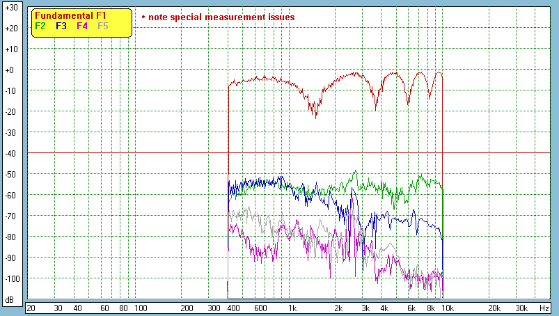
Distortion graph from Zaph website (absolute scale may be off
some according to his website)
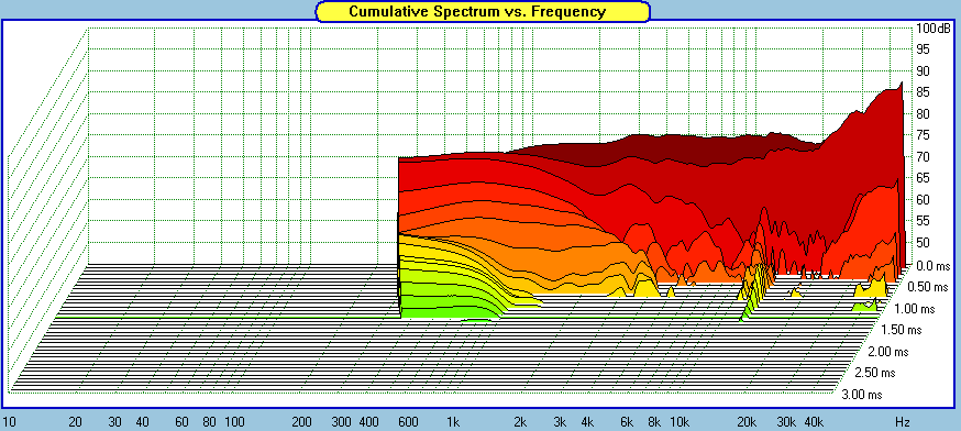
CSD graph of Millenium dome tweeter from Zaph website
The Electronics
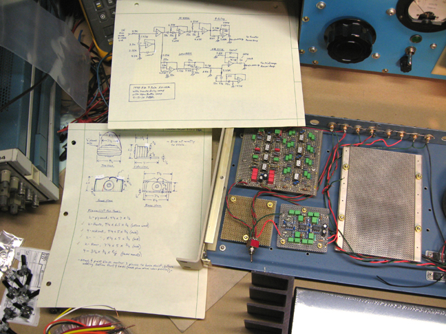
The big loaded board above is my variation of the Carver hologram
circuit.

3 way 4 pole active crossover network and active woofer EQ,
Open-Baffle EQ and Carver style Holographic Generator (can be bypassed)
Since I'm not a software engineer, all my circuits are analog.
Below is the actual measured frequency response of the crossover
circuit.
The midrange part is lower because of an efficiency difference.
Four 5 inch drivers have about 6dB more efficiency than one,
but because of how they are wired (series/parallel) about 3dB in this case.
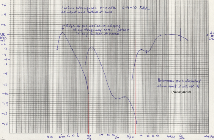
The Y axis is dB. The red vertical lines are the actual crossover
frequencies.
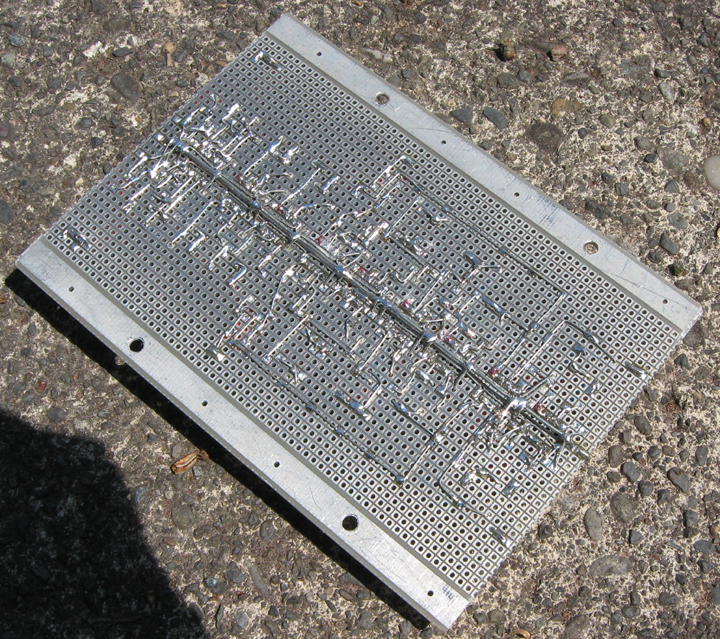
The bottom of one of the boards I built into the crossover
chassis.
Acoustics 101
The "comb Filter" effect
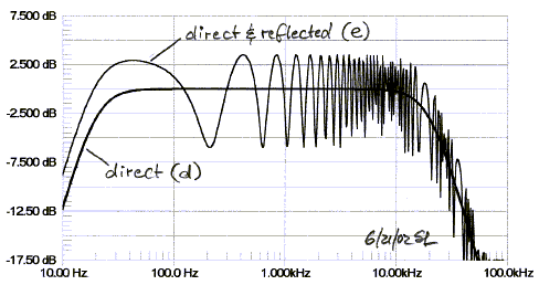
In the case where there is one reflected acoustic signal mixing
at your ear with a direct acoustic signal, you get a frequency response issue
as in the graph below.
At the frequency where the delay of the reflected signal is
a half wavelength, you'll get a substantial cancellation when the two signals
add at your ear.
Due to the laws of physics, you'll also get cancellations at
all the integral multiples of that "fundamental" frequency.
At higher frequencies where the energy gets more easily absorbed
by the room surfaces and furnishings, the cancellations are typically less drastic.
12dB cancellations right in the midrange frequencies are not
rare, based on my 1st hand experience.
This drawing only shows a 5dB cancellation depth. I beilieve
it's a theoretical drawing, not an actual measurement.
This will be worse in smaller rooms.
Here's one example of how a room destroyed an otherwise very
flat speaker system
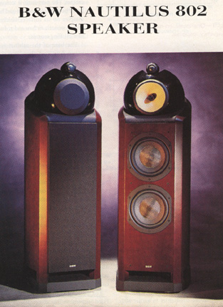
A high end speaker system
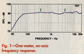
It's frequency response measured up close
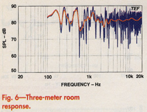
Same speaker measured further back, in a relatively typical
listening room,
with the calibrated mic about where a typical listener would
be located.
Most listening rooms will butcher the frequency response of
any speaker. Especially smaller rooms.
There's both the combfilter effects, and room resonances, only
the latter rings.
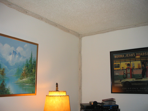
I found that putting acoustically absorbtive material (2 inch
cotton rope or foam rubber) in the corners of the room reduced room ringing
substantially.
I used the hand clap test for this, and the difference was
obvious and big.
Comb filter cancellations average out better (get filled in)
in "live" rooms (rooms with lots of relfections). This is typically
true for frequencies above about 400HZ.
From about 80HZ - 400HZ, depending on the room, there will
usually be so few effective reflections, due to the size of the wavelengths
and room dimensions,
that there is likely to be some bad frequency response issues
in the lower midrange/upper bass frequencies that typically cause "boominess".
"Boominess" is usually more because of the room acoustics,
than the speaker itself. Below 80HZ, my room had no problems of any significance.
If you decide to use a graphic or parametric active EQ to even
out the response (only recommended for below about 300HZ),
you can attenuate peaks, but trying to pull up cancellations
doesn't really work and causes problems. You would create peaks elsewhere in
the room.
Moving the woofers to different locations can be the best way
to even out the lower mid/upper bass issues, which is why I prefer the Satalite/Subwoofer
arrangement.
I don't recommend puting woofers in a 3 surface corner. You'd
get more SPL per watt, but it stimulates room acoustics issues more.

Old photo of Setup in my living room, with previous tweeter
towers.
Things I learned from this system:
Although I thought they sounded quite good when seated in just
the right place, especially with the Hologram circuit enabled, I realized that
the lower midrange rolls off when you're off axis,
which means anyone not sitting in the right place (centered),
will hear a colder sound. My friends who sat off axis were not impressed.
Also the midrange to tweeter integration could have been better.
In a larger room these speakers might have been great, but in my apartment not
the best.
I eventually parted them out, and used the drivers in other
systems, which worked much better in this room.


