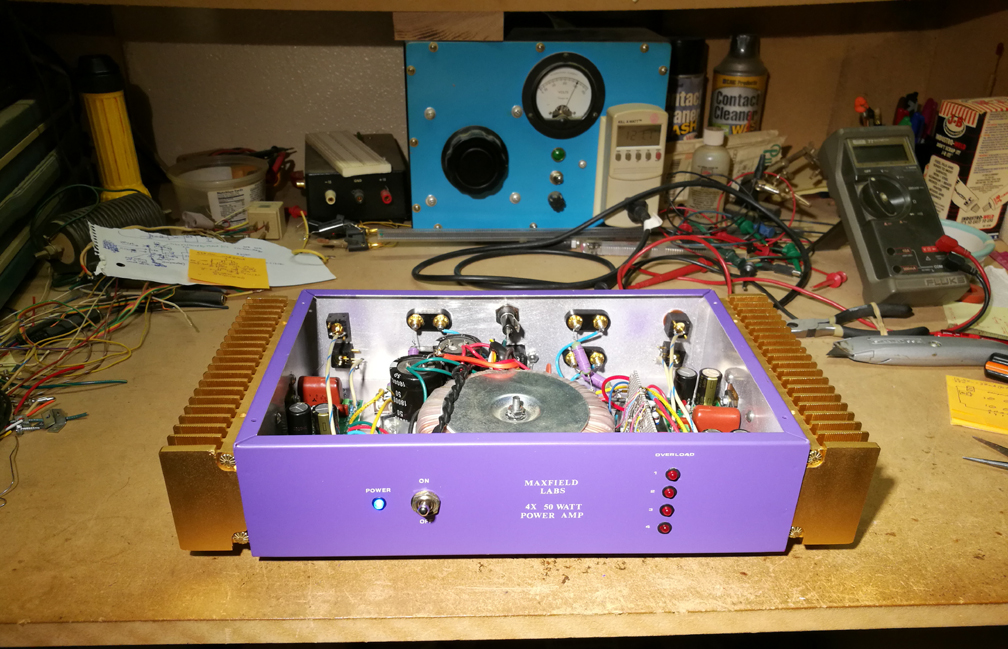
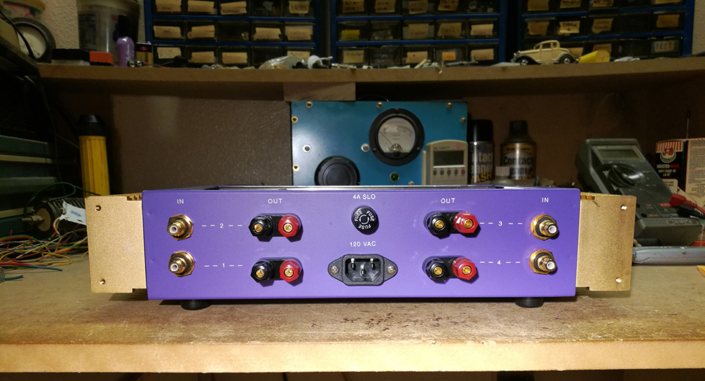
by Bob Richards of Maxfield Laboratories 2020


I already built one of these several years ago, virtually identical except for the overload indicator board. Finding heatsinks that I really like took a while. The only ones I really liked, I had to buy directly from Hong Kong. I'd never bought anything directly from China before, so I wasn't sure what to expect. It went smooth, no duty fees or anything. With shipping costs, the price was still reasonable. These days, building a poweramp is probably not cheaper than just going out and buying one already built (even though these chips cost less than $10 each), but I wanted to use the LM3886 poweramp chips for the following reasons:
There was a time when integtrated circuit poweramps were not real good, just like early transistor amps, and the earliest tube amps. Since the mid 1980's I think most designs involving transistors were plenty good. Linkwitz, mentioned above, was a very well educated EE, and was as picky about everything as anybody. If you're the kind of person who wants to use an active crossover, with a separate poweramp for each driver in a speaker system, you don't need a huge amount of power for midrange and tweeter drivers, but you do need a total lack of turn on and turn off transients (which could seriously damage a tweeter, and possibly even a small midrange driver). And a very low DC offset at the output. The other thing that is real nice to have, is many channels in one chassis. These chips require very few external parts to make them sing, so it's pretty easy to fit four of them in a box that's fairly small.
The differences should be tiny if they are designed well, and optimmized for maximum fidelity. What we have in the real world are variable output impedance, Push-pull crossover distortion, flimsy phase margins, Rf energy suseptability, minimal cost parts, and really fancy front panels and connectors that cater to the power of suggestion.
Low feedback tube amplifiers, the sound of which many prefer, have higher output impedance ("source impedance") which allows the electro-mechanical speaker driver to act out it's resonances a bit, which in most cases makes a speaker sound more warm, since a typical baffled woofer usually has a substantial impedance rise (peak) in the general vacinity of 50-60 HZ. The lower the output impedance the amp has, the more tightly it controls the speaker driver diaphram, which means higher fidelity. Personally I prefer the tighter control. I prefer tight clean bass, and minimally resonant midrange reproduction. Some say the sound is then too "clinical" or "cold". I disagree with that. Fidelity is fidelity. Program source material is often mixed poorly, and is more likely the source of any "clinical coldness".
In the 1960's and even 70's, many engineers didn't have a good grasp on what Phase Margin is and how to optimize it, so poweramps would occasionally blow up, often blowing the speakers too. The same negative feedback that cleaned up the distortion to very low levels, would become positive feedback at some very high frequency, due to phase shifts adding up, usually beyond the frequencies we can hear, and the amp would turn into a supersonic oscillator. When the feedback would try to correct for this, it would cause the explosion. Phase Linear, SWTPC, and the Dynaco 120 are some examples with this weakness.
Many power amps have serious trouble handling Rf energy applied to their inputs. The least of what happens is that the energy gets asymetrically slewed and/or clipped, which generates Intermodulation distortion (I.M. Dist.). What is also often likely is that the amp might blow up, when it's high feedback circuit tries to correct for what the Rf energy causes, much like with the poor phase margin issue mentioned above. These days a lot of program content is from a digital source, which can have left over Rf energy, after conversion back to analog. So I always put a passive Rf filter at the input of any preamp or poweramp I build. Many don't.
I use what good Engineers would call "high-end" parts, but not the esoteric "boutique" versions that have the high prices. Metal film resistors contribute less hiss noise. I always use metal films unless in an output or power supply circuit. Capacitors with Polypropylene or polystyrene dielectrics have extremely low distortion. I don't really know of a bad brand for those types of parts. Understanding why a given topology will work best is a very important part of the process. It's my opinion that you almost never need to spend a lot of money on esoteric versions of these parts, to build something that competes well with the best out there. The toroidal power transformers emit a LOT less electromagnetic radiation than the EI or C core transformers. They used to be expensive but any more not really. The Toroid used in this project cost about $100, but handles 200 watts rms at 8 ohms worth of audio output power, good enough for me. Getting the grounding system right can be very significant. Having a separate power supply for each channel is extremely unlikely to make an audible difference in a home based Hi-fi system. That could be worth it if you're doing sound for a rock festival, where everything gets pushed close to its limit.
Connectors are an area where there can be significant distortion production. I went for the gold plated RCA connectors since gold never corrodes, but what's also important, is what type of metal it will be in contact with when the input cables are plugged in. Certain metal combinations can have molecular migration issues over time, which can cause significant non-linear distortions to creep in. Rarely a big problem, but I've seen it be, so I give it some thought. The Banana jacks I use for the output connectors are great, but how you attach the wires to the banana plugs can be an issue. That typical little set screw clamping down on the wire (even if the wires are twisted, solder saturated and alcohol cleaned - as they should be) can become non-linear over time. I solder my wires to the banana plug if there's any way to do that, so that part of the connection won't turn nonlinear resistive over time.
"The LM3886 based amplifiers on the PLUTO pcb board are another option. They actually measure quite a bit better than the Emotiva UPA-500 or MINI X-A100 for low distortion at 1 W and 100 mW levels."
"In Class A/B power amplifiers the time variant and amplitude dependent [push-pull] crossover distortion is more harmful than harmonic distortion, because of its impulsive and thus wideband nature. It does not register in the typical high signal level harmonic distortion specification. Crossover distortion changes with bias conditions and is thus a function of the thermal control loop of the amplifier. It must be tested dynamically as output power switches from high to low levels and device temperatures change."
"Solid-state power amplifiers are, by no means, automatically superior to tube amplifiers. Some of the early designs had notoriously high distortion levels of a character unknown with tubes. I also contend that design and construction of a highly transparent solid-state amplifier is far more difficult than that of an an acceptably sounding tube power amplifier. The difficulties of controlling the inherent non-linearities, wide bandwidth, thermal coupling and stability under all conditions of voltage and current swing, and load, are a real challenge even to an experienced analog design engineer, and require not only a solid understanding of devices, feedback control theory, radio frequency electronics and thermal design, but also extensive measurement capability. This is why I recommend to the DIYer power op amps like the LM3886, where all these aspects have been resolved and integrated at the chip level, thus greatly simplifying the remaining external circuitry."
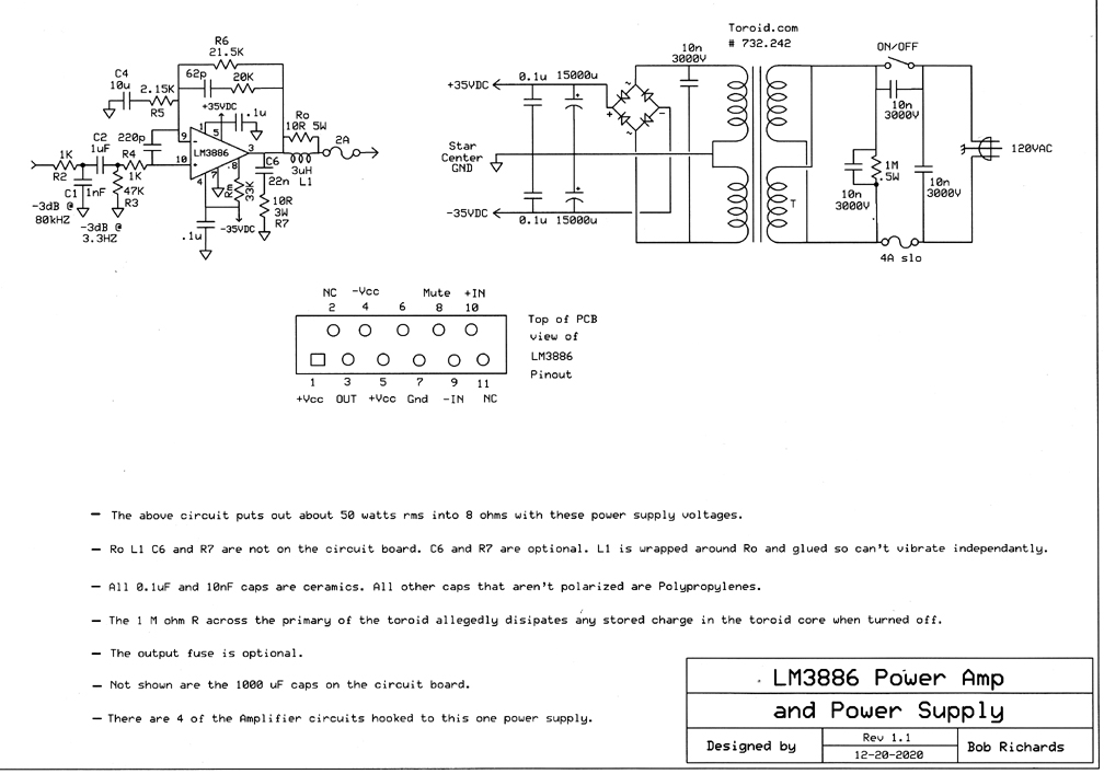
Some people say the output speaker fuse damages the sound quality. I'm not convinced that the difference is audible, but I do agree that by the time the fuse blows, the speaker has usually blown too.
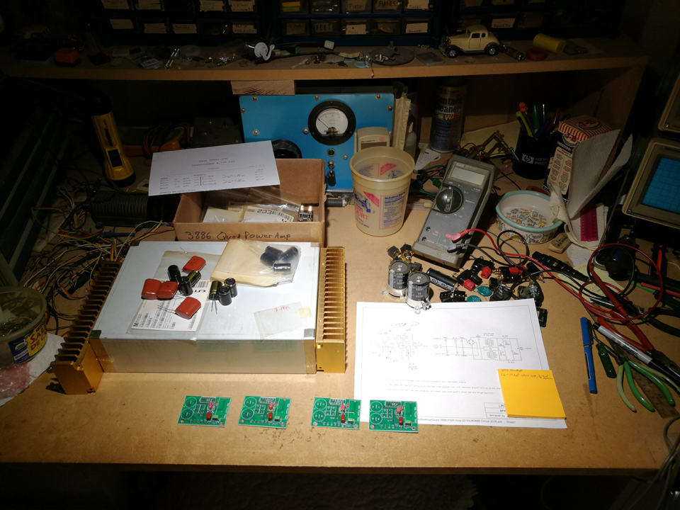
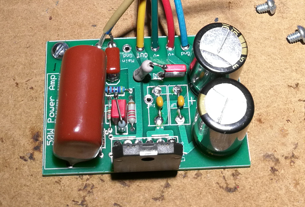
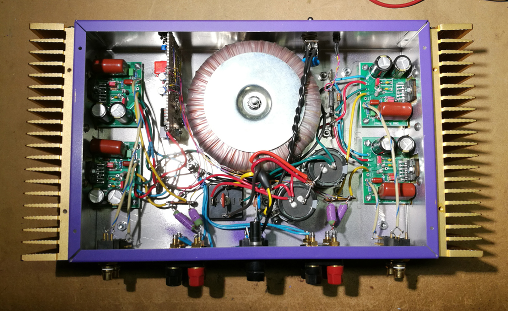
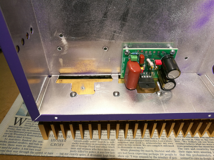
In order to keep part lead lenths as short as possible (always a good idea), 2 parts are mounted on the bottom of the 3886 circuit board.
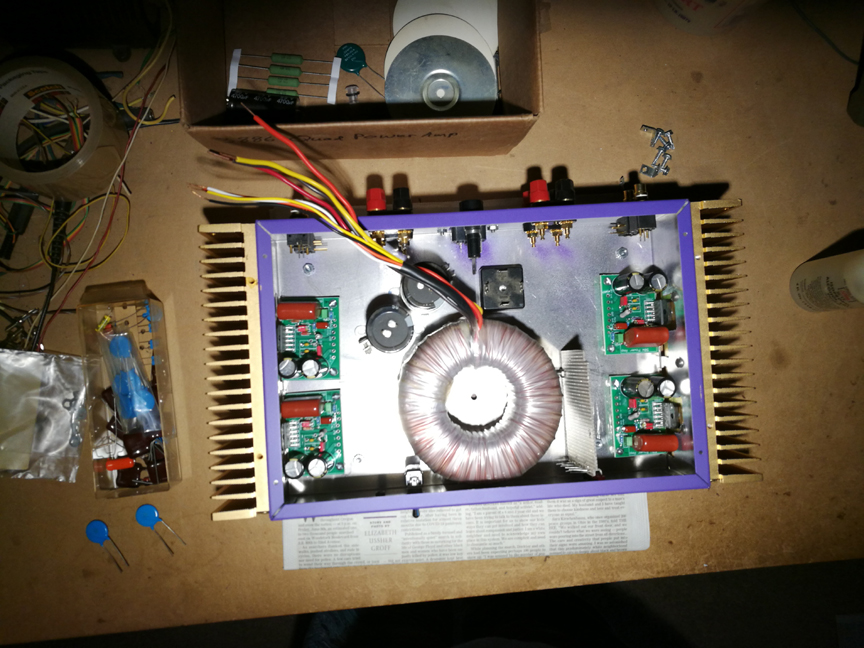
Above on the left, I'm figuring out exactly where everything should go physically.
On the right, I'm making sure that the position of the circuit board/chassis screw holes, don't cause stress on the 3886 chip pins, when the chip is bolted to the heatsink.
This time I bought the version of the LM3886 chip that doesn't need an insulator and heat transfer compound at the heatsink.
At max power output, this design doesn't push the 3886 anywhere near its power limit. Power supply voltage could be significantly higher.
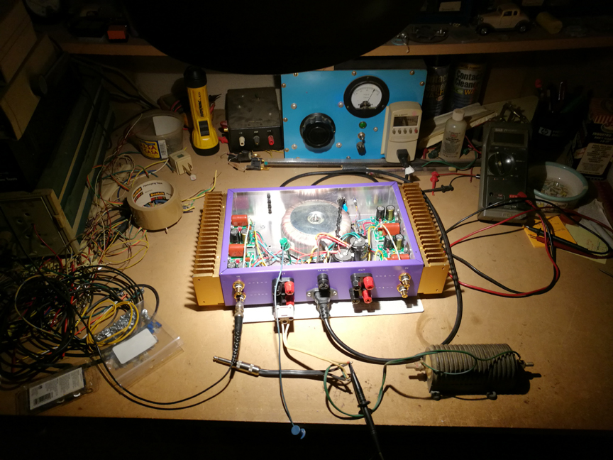
Since hot air rises, it makes best sense to have heat sinks with vertical fins, so it can flow easier.
Here I am testing each channel, before building the overdrive indicator board.
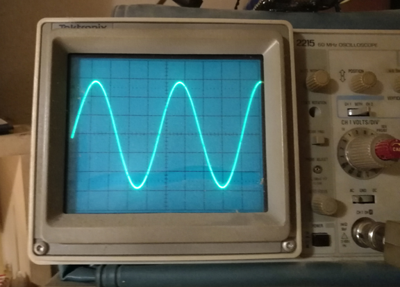
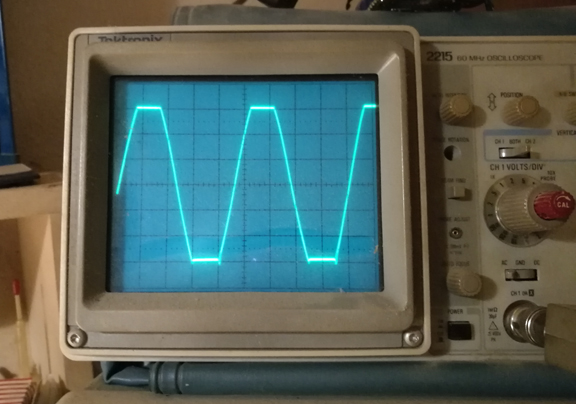
Above on the left is maximum clean power, 49 watts rms, into my 10 ohm load resistor.
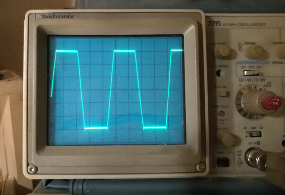
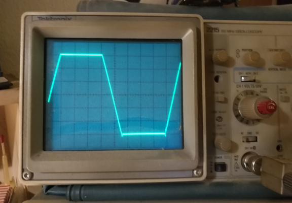
How an amplifier recovers from overdrive is a very important part of the evaluation process.
Some amplifiers will show significant spurious oscillations in the waveform, as they come out of clipping.
That would indicate a less stable feedback circuit. The oscillations are typically at frequencies above the audio frequency spectrum, and can be well into the mHZ.
Such oscillations aren't directly audible, but can cause audible distortions as a side effect, and have been known to burn out tweeters.
In a worse case scenario, these oscillations can cause a poweramp to blow up, and blow the speakers too. Been there, done that, back in the 1970's.
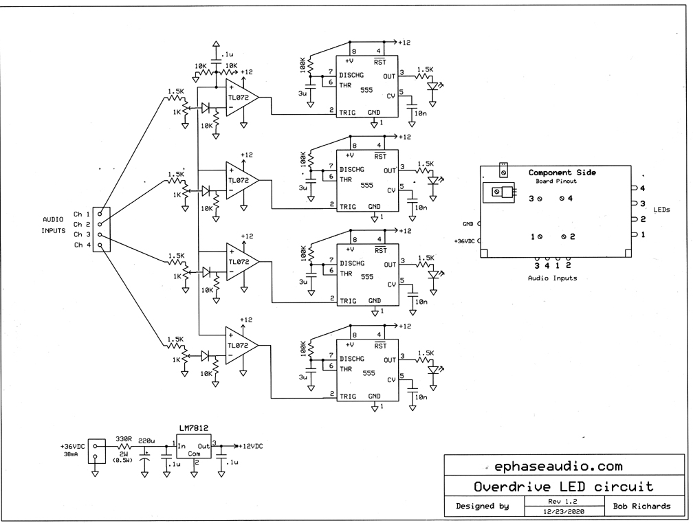
Although this circuit can respond plenty fast to catch even the shortest transient that causes clipping, the 555 chip wired as a monostable multivibrator, causes the red LED to stay on for a minimum of about 1/2 second.
That way you can always tell when to back off the volume, so everything stays clean.
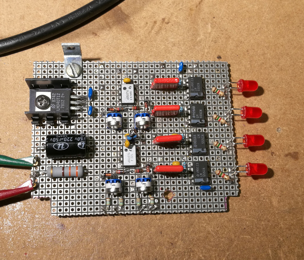
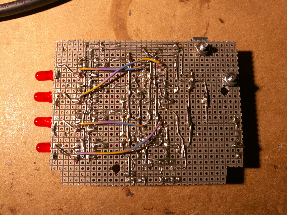
I'm using TL072 dual op-amps as comparators.
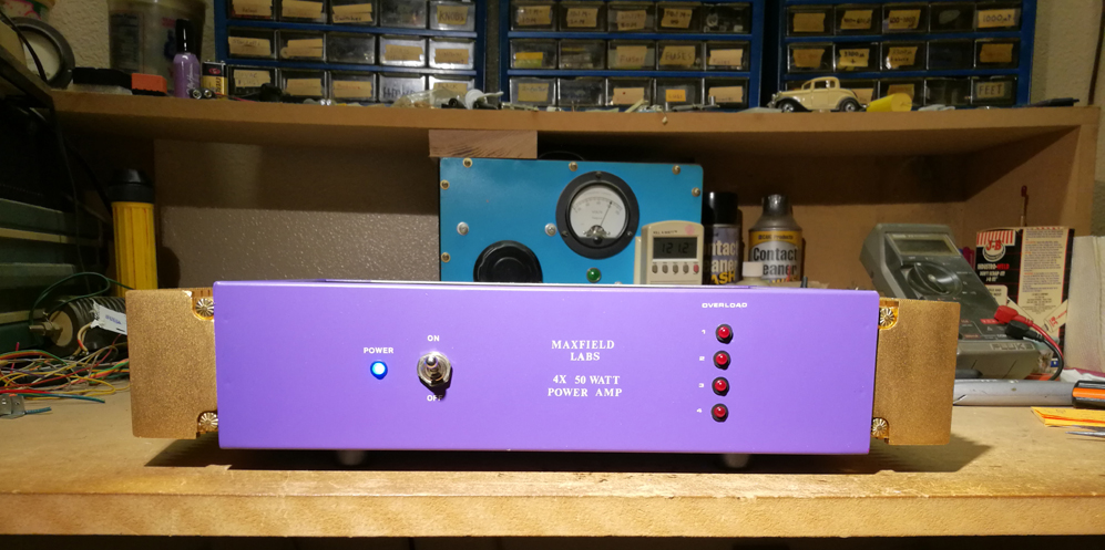
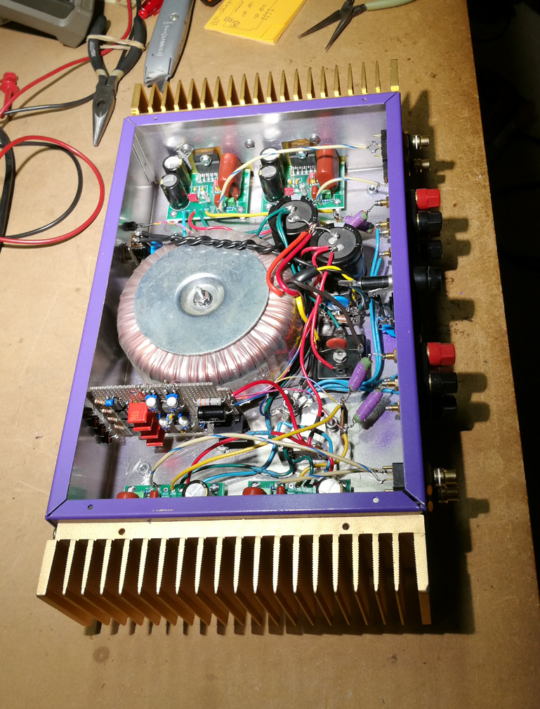
Below are a few more pictures of the finished product.
